Disassembly and assembly device

A technology for equipment and disassembly and assembly of components, which is applied in the direction of lifting devices, lifting frames, workbenches, etc., can solve problems such as easy deformation and lack of support force, and achieve the goal of improving satisfaction, wide application range, and improving maintenance and disassembly efficiency Effect

Inactive Publication Date: 2020-07-28
CHINA RAILWAY CONSTR HEAVY IND
View PDF7 Cites 4 Cited by
  • Summary
  • Abstract
  • Description
  • Claims
  • Application Information

AI Technical Summary

Problems solved by technology

[0002] The dismounting equipment that present maglev train is used usually supports the supporting platform by lifting device, and then realizes the support to the parts (such as suspension frame) of magnetic levitating train, because lifting device is arranged on the edge place of supporting platform usually, makes The support platform is prone to deformation due to the lack of support in the middle part under stress

Method used


Image

  • Disassembly and assembly device
  • Disassembly and assembly device
  • Disassembly and assembly device

Examples


Embodiment 1

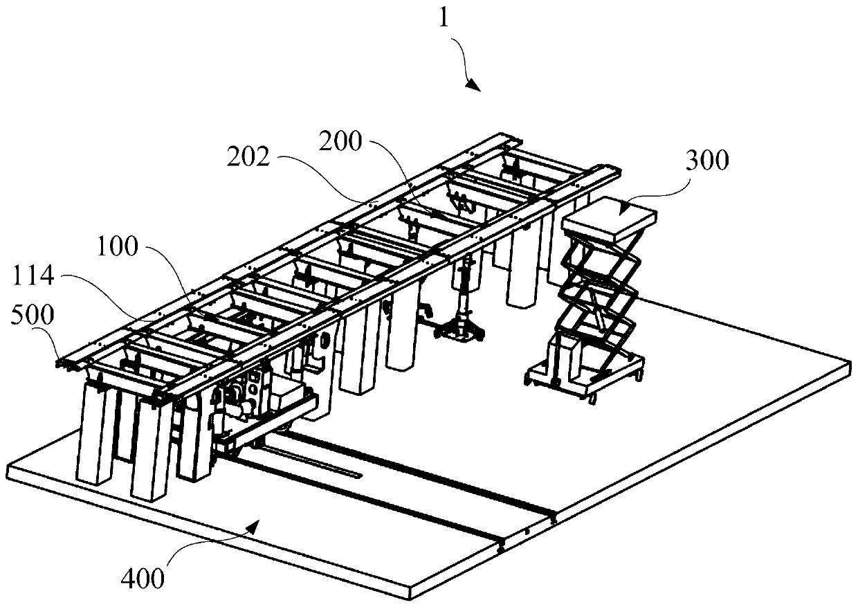
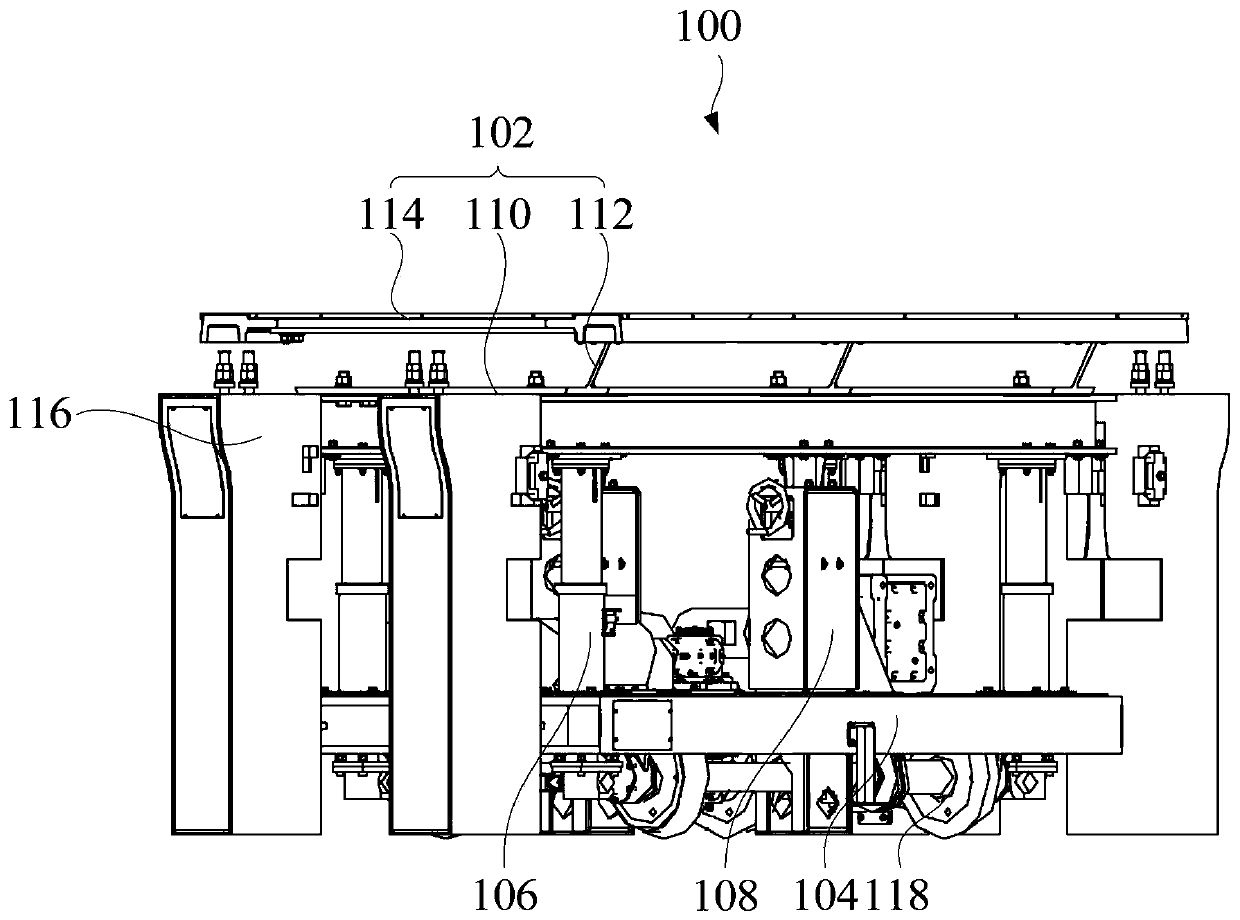
[0069] like Figure 1 to Figure 8 As shown, the embodiment of one aspect of the present invention proposes a disassembly equipment 1, including: a first support platform 102, a first support 104, a first lifting device 106, a second lifting device 108, wherein the first support 104 Located below the first support platform 102; the first lifting device 106 connects the first support platform 102 and the first support 104, and is configured to adjust the distance between the first support platform 102 and the first support 104; the second lift The device 108 is located on one of the first support platform 102 and the first support 104, and is located between the first support platform 102 and the first support 104. The second lifting device 108 is configured to be suitable for the first support platform 102 and the first support platform 102 The other one of the first brackets 104 abuts against each other; wherein, the first lifting device 106 is arranged on the edge of the firs...

Embodiment 2

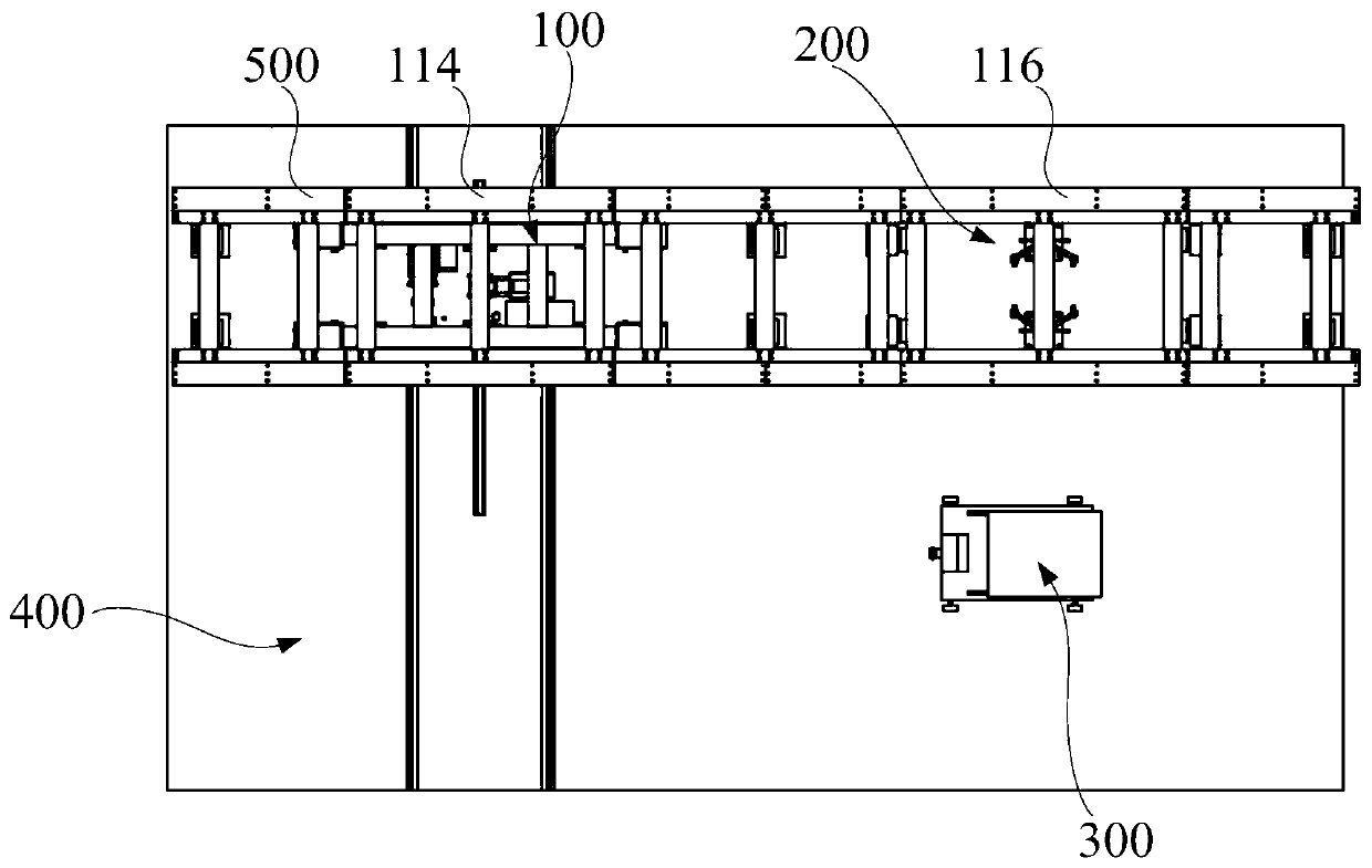
[0073] like Figure 1 to Figure 8As shown, on the basis of the above-mentioned embodiment 1, further, the first support platform 102 includes: a first beam 110, two first beams 110 are arranged in parallel, along the length direction of the first beam 110, the first lifting device 106 Distributed on both sides of the second lifting device 108; the second beam 112 is connected with the first beam 110 and is located between the two first beams 110; the first track 114 is connected with the first beam 110 , and located on the side of the first beam 110 away from the first lifting device 106; the first column 116, the end of the first beam 110 is detachably connected to the first column 116.

[0074] In this example, image 3 and Figure 4 As shown, the first support platform 102 includes a first beam 110, a second beam 112, a first rail 114 and a first column 116, wherein the two first beams 110 are arranged in parallel, and the second beam 112 is opposite to the first beam 110...

Embodiment 3

[0078] like Figure 1 to Figure 8 As shown, on the basis of the above-mentioned embodiment 1 or embodiment 2, further, the first assembly and disassembly assembly 100 further includes: a first walking assembly 118 connected to the first bracket 104; a belt transmission assembly 120 arranged on the second A frame 104 is connected with the first traveling assembly 118 , and the belt transmission assembly 120 is configured to drive the first traveling assembly 118 .

[0079] In this example, image 3 and Figure 4 As shown, by connecting the first walking assembly 118 to the first support 104, the first walking assembly 118 can be moved to realize the horizontal movement of the suspension frame connected to the first beam 110, so as to move the suspension frame to a designated position. The belt transmission assembly 120 is located on the first support 104 and is connected with the first walking assembly 118. The driving speed of the first walking assembly 118 can be adjusted b...


PUM


Abstract

The invention provides a disassembly and assembly device. The disassembly and assembly device comprises a first disassembly and assembly assembly, the first disassembly and assembly assembly comprisesa first supporting table, a first support, a first lifting device, and a second lifting device, the first support is mounted below the first supporting table, the first lifting device is connected with the first supporting table and the first support, and is configured to adjust the distance between the first supporting table and the first support, the second lifting device is mounted on one ofthe first supporting table and the first support, is located between the first supporting table and the first support and is configured to be suitable for being in abut joint with the other one in thefirst supporting table and the first support, the first lifting device is mounted on the edge of the first supporting table, the second lifting device is mounted in the middle of the first supportingtable or is configured to be suitable for being in abut joint with the middle of the first supporting table, according to the disassembly and assembly device, through the second lifting device, supporting of the middle of the first supporting table is achieved, and the first supporting table is uniform in stress and is not prone to deforming under the stress condition.

Description

technical field [0001] The invention relates to the technical field of assembly and disassembly of magnetic levitation train components, in particular to a disassembly and assembly equipment. Background technique [0002] The dismounting equipment that present maglev train is used usually supports the supporting platform by lifting device, and then realizes the support to the parts (such as suspension frame) of magnetic levitating train, because lifting device is arranged on the edge place of supporting platform usually, makes The support platform is prone to deformation due to the lack of supporting force in the middle part under the condition of force. Contents of the invention [0003] The present invention aims to solve at least one of the technical problems existing in the prior art or related art. [0004] To this end, one aspect of the present invention proposes a dismounting device. [0005] In view of this, an aspect of the present invention proposes a disassemb...

Claims


Application Information

Patent Timeline
Patent Type & Authority Applications(China)
IPC IPC(8): B25B27/00B25H1/16B66F7/06
CPCB25B27/00B25H1/16B66F7/0666
Inventor 刘飞香罗建利陈兵生郑开柳宗斌
Owner CHINA RAILWAY CONSTR HEAVY IND
Why Eureka
Try Eureka