Stamping die for front suspension left-right upper bracket inner side plate

A stamping die and stamping column technology, which is applied in the field of stamping dies for the inner side panels of the left and right upper brackets of the front suspension, can solve the problems of affecting the service life of the dies, high pressure of the upper and lower dies, and low stability, and achieves compact structure, reduced stamping pressure, Improve the effect of using diversity

Pending Publication Date: 2020-04-17
十堰帝尔科技有限公司
View PDF0 Cites 0 Cited by
  • Summary
  • Abstract
  • Description
  • Claims
  • Application Information

AI Technical Summary

Problems solved by technology

[0002] Most of the traditional stamping dies are fixed in one form. When stamping, the stability is not high, and when stamping with a fixed form of stamping die, the

Method used


Image

  • Stamping die for front suspension left-right upper bracket inner side plate
  • Stamping die for front suspension left-right upper bracket inner side plate
  • Stamping die for front suspension left-right upper bracket inner side plate

Examples


Embodiment 1

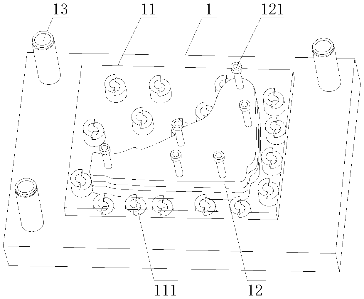
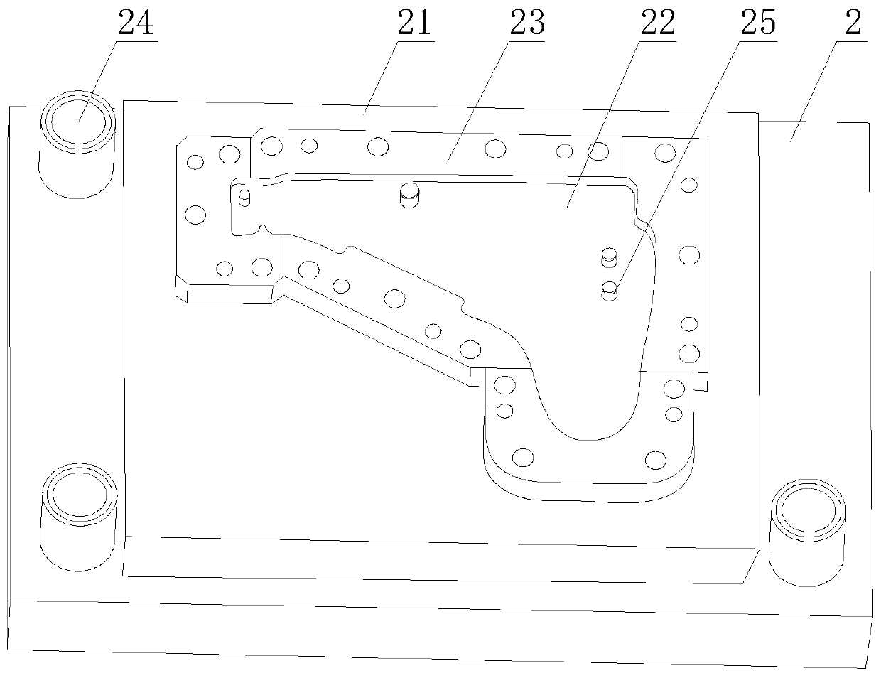
[0023] see Figure 1-2 , a stamping mold for the inner side plate of the left and right upper brackets of the front suspension, comprising an upper die base 1 and a lower die base 2, an upper backing plate 11 is installed on the upper die base 1, an upper template 12 is connected to the upper backing plate 11, and an upper die base 1 is The stamping column 13 is installed on the side, the upper end of the upper backing plate 11 is provided with a guide column 111, the upper template 12 is provided with a stamping rod 121, the lower backing plate 21 is installed on the lower mold base 2, the lower template 22 is installed on the lower backing plate 21, and the outer side of the lower template 22 Cover the butt plate 23, the butt plate 23 is installed on the lower backing plate 21, the guide hole 24 is set on the lower mold base 2, the guide hole 24 is set on the butt plate 23, the punching groove 25 is set on the lower template 22, and the upper backing plate 11 passes through ...

Embodiment 2

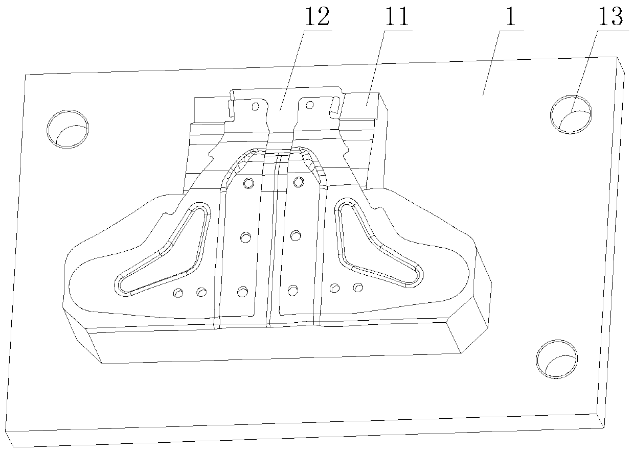
[0025] see Figure 3-4 , the structure of the upper formwork 12 and the lower formwork 22 is a T-shaped symmetrical structure, and the upper formwork 12 is arranged in the upper backing plate 11, two pairs of triangular grooves are opened on the upper formwork 12, and the upper formwork 12 and the lower formwork 22 of the symmetrical structure , The symmetrical structure reduces the stamping pressure and reduces the wear of the mold, and different mold structures meet the needs of different structures and increase the diversity of use.

Embodiment 3

[0027] see Figure 5-6 , the upper backing plate 11, the upper formwork 12 and the lower formwork 22 are half-angle structures, and are all arranged at the opposite corners of the upper mold base 1, and the butt plate 23 covers the lower formwork 22 and the lower backing plate 21 inside, and the butt plate 23 is provided with a docking groove, and the upper backing plate 11 and the upper template 12 are docked with the docking groove. By covering the upper backing plate 11 and the upper template 12 with the butt plate 23 for guidance, the overall structure of the guide column 111 is reduced, which is more convenient and compact. Reasonable design, increase punching space.

[0028] To sum up: in the present invention, the stamping mold for the inner side plate of the left and right upper brackets of the front suspension, the height of the lower template 22 is lower than the butt plate 23, and the butt plate 23 wraps the butt plate 23 inside to form a lower die groove 221. The ...


PUM


Abstract

The invention discloses a stamping die for a front suspension left-right upper bracket inner side plate, which comprises an upper die holder and a lower die holder, wherein an upper base plate is arranged on the upper die holder, an upper die plate is arranged on the upper base plate, a stamping column is arranged on an upper side edge of the upper die holder, a guide column is arranged at an upper end of the upper base plate, and a stamping rod is arranged on the upper die plate; a lower base plate is arranged on the lower die holder, a lower die plate is arranged on the lower base plate, anda butt-joint plate, arranged on the lower base plate, is covered on the outer side of the lower die plate. The stamping die for the front suspension left-right upper bracket inner side plate is stable in work in stamping, the product forming precision and efficiency can be effectively improved, and the product resilience phenomenon can be reduced; the rejection rate is low, the production can bereduced, and the enterprise economic benefit can be improved; a symmetric structure can reduce the pressure of the stamping and reduce the abrasion of the die; and different die structures meet different structure requirements, the use diversity is improved, the structure is compact, the design is reasonable, and the stamping space is increased.

Description

technical field [0001] The invention relates to the technical field of stamping dies, in particular to a stamping die for the inner side plates of the left and right upper brackets of the front suspension. Background technique [0002] Most of the traditional stamping dies are fixed in one form. When stamping, the stability is not high, and when stamping with a fixed form of stamping die, the pressure on the upper and lower dies is large, and the wear is serious, which affects the service life of the die. The product quality is poor and the production efficiency is low. Contents of the invention [0003] The object of the present invention is to provide a stamping die for the inner side plate of the left and right upper brackets of the front suspension, which works stably during stamping, can effectively improve the precision and efficiency of product forming, and can reduce the phenomenon of product springback, and the scrap rate is low, which is beneficial to reduce Pro...

Claims


Application Information

Patent Timeline
IPC IPC(8): B21D37/10B21D37/12
CPCB21D37/10B21D37/12
Inventor 孟广学田龙虎邓超秦晓君
Owner 十堰帝尔科技有限公司
Why Eureka
Try Eureka