
current detection circuit

A technology of current detection circuit and power supply, applied in the direction of measuring current/voltage, measuring device, measuring electric variable, etc., can solve the problems of increasing volume and cost, and achieve the effect of large reverse resistance

Active Publication Date: 2015-10-07
SUZHOU HUAZHIJIE TELECOM
View PDF4 Cites 0 Cited by
  • Summary
  • Abstract
  • Description
  • Claims
  • Application Information

AI Technical Summary

Problems solved by technology

[0003] The current detection part below not only increases the volume and cost of components

Method used


Image

  • current detection circuit
  • current detection circuit

Examples


Embodiment Construction

[0009] Specific embodiments of the present invention will be described in detail below in conjunction with the accompanying drawings.

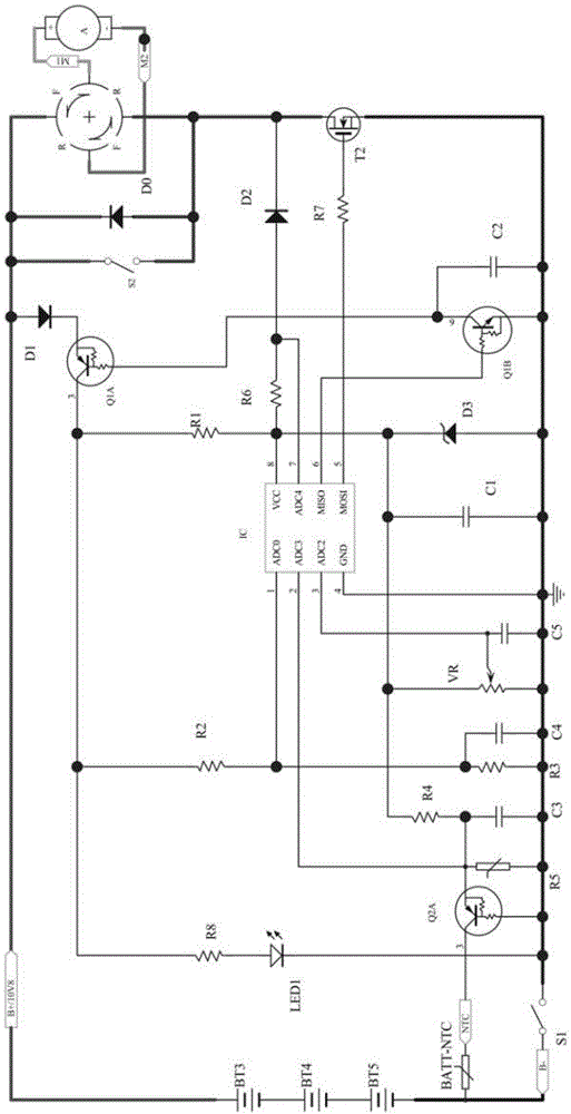
[0010] Such as figure 2 As shown, the current detection circuit of the present invention includes a circuit composed of a power supply, a switch S1, a MOS transistor T2 and a motor, and the circuit is also provided with a microprocessor IC, a first resistor R1 and a diode D2, and the MOS transistor T2 The D pole of the MOS tube T2 is connected to the motor, the S pole of the MOS tube T2 is connected to the negative pole of the power supply, the second resistor R6 is connected between the 8th pin VCC end and the 7th pin of the microprocessor IC, and one end of the first resistor R1 is connected to the micro The 8th pin of the processor IC is connected to the VCC terminal, the other end is connected to the positive pole of the power supply, the positive pole of the diode D2 is connected to the 7th pin of the microprocessor IC, the negative pole...


PUM


Abstract

The invention discloses a current detection circuit which has few elements, is good in detection effect and comprises a circuit. The circuit comprises a power source, a switch, an MOS (metal oxide semiconductor) transistor and a motor, a microprocessor, a first resistor and a diode are further arranged in the circuit, an electrode D of the MOS transistor is connected with the motor, an electrode S of the MOS transistor is connected with a cathode of the power source, a second resistor is connected between an eighth pin and a seventh pin of the microprocessor, one end of the first resistor is connected with the eighth pin of the microprocessor, the other end of the first resistor is connected with an anode of the power source, an anode of the diode is connected with the seventh pin of the microprocessor, a cathode of the diode is connected with the electrode D of the MOS transistor, and an electrode G of the MOS transistor is connected with a fifth pin of the microprocessor by a third resistor. The current detection circuit has the advantages that the microprocessor can be effectively protected from interference of high voltage and the motor owing to the unilateral conductivity of the diode, the diode is extremely high in back resistance and is nearly free of leak current, and accordingly the performance of the diode can be played to the greatest extent by the current detection circuit.

Description

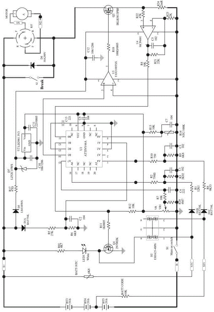
technical field [0001] The invention relates to a current detection circuit. Background technique [0002] Most of the speed control switch control circuits in the market now have the same figure 1 The structure of the circuit is complex and expensive. And has the following defects: [0003] The current detection part below not only increases the volume and cost of components. And the current flowing through R24 is very large, so the heat is very fast. An increase in ambient temperature inside the switch affects the stability of the entire control board. Contents of the invention [0004] The technical problem to be solved by the invention is to provide a current detection circuit with few components and good detection effect. [0005] In order to solve the above-mentioned technical problems, the technical solution adopted by the present invention is: a current detection circuit, including a circuit composed of a power supply, a switch, a MOS tube and a motor, and a m...

Claims


Application Information

Patent Timeline
Patent Type & Authority Patents(China)
IPC IPC(8): G01R19/00
Inventor 于盛
Owner SUZHOU HUAZHIJIE TELECOM
Learn More