Transparent liquid crystal display device
A technology of transparent liquid crystal display and liquid crystal layer, used in static indicators, instruments, nonlinear optics, etc., can solve the problems of low contrast, insufficient black state, unable to solve transparent display, etc., and achieve the effect of high contrast and high transparency
- Summary
- Abstract
- Description
- Claims
- Application Information
AI Technical Summary
Problems solved by technology
Method used
Image

Examples
no. 1 example
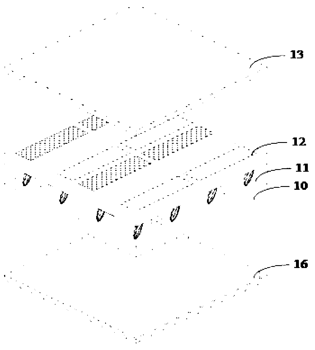
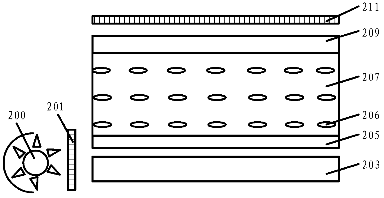
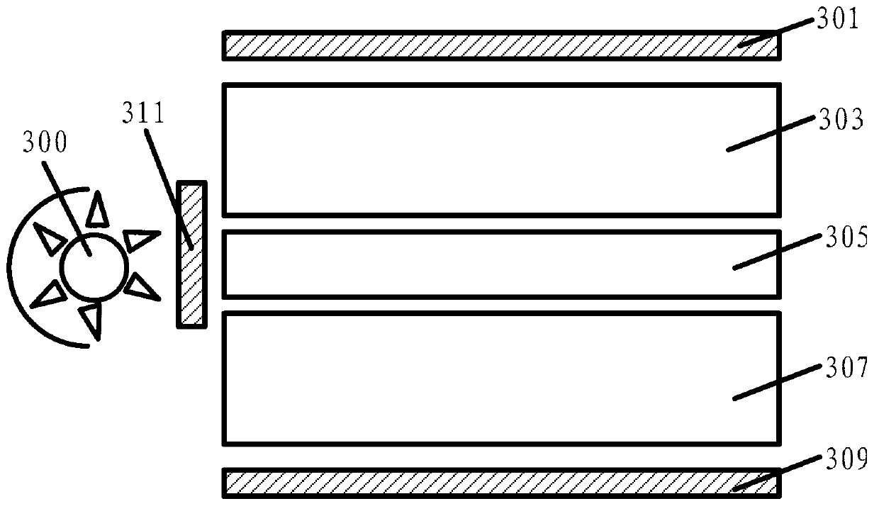
[0050] Please refer to image 3 (For ease of drawing, only the structure of one pixel unit is shown in the embodiment of the present invention), the transparent liquid crystal display device in the embodiment of the present invention has a plurality of pixel units, and the transparent liquid crystal display device includes:
[0051] A first liquid crystal layer 303, and a first polarizer 301 located above the first liquid crystal layer 303;
[0052] a transparent light guide plate 305 located below the first liquid crystal layer 303;
[0053] A backlight 300 located on one side of the transparent light guide plate 305, a second polarizer 311 is arranged between the backlight 300 and the transparent light guide plate 305;
[0054] The second liquid crystal layer 307 is disposed below the transparent light guide plate 305 , and a third polarizer 309 is disposed below the second liquid crystal layer 307 .
[0055] Wherein, the first liquid crystal layer 303 and the second liqui...
example 1
[0059] In Example 1 of the present invention, the first polarizer 301 is set to allow the polarized light in the P direction to pass; different from the first polarizer 301, the second polarizer 311 and the third polarizer 309 are set to Polarized light in the S direction, which is perpendicular to the P direction, is allowed to pass.
[0060] The inventor found that, in Example 1 of the present invention, after the light from the backlight 300 passes through the second polarizer 311, only the polarized light in the S direction remains. When no voltage is applied to the first liquid crystal layer 303, the backlight 300 The polarized light in the S direction is deflected by 90 degrees after passing through the first liquid crystal layer 303, and becomes the polarized light in the P direction, which can pass through the first polarizer 301; when a voltage is applied to the first liquid crystal layer 303, the backlight The polarized light in the S direction in the source 300 is n...
example 2
[0087] Please continue to refer image 3 , in Example 2 of the present invention, different from Example 1, the first polarizer 301 is set to allow the polarized light in the P direction to pass through, and the second polarizer 311 is set to allow the polarized light in the S direction to pass through, the The third polarizer 309 is configured to allow polarized light in the P direction to pass through.
[0088] When no voltage is applied to the first liquid crystal layer 303 of the pixel unit, no matter whether a voltage is applied to the second liquid crystal layer 307, the light in the backlight 300 can pass through the first polarizer 301 of the pixel unit and enter the user’s Line of sight, the pixel units are all displayed in a white state; when a voltage is applied to the first liquid crystal layer 303 of the pixel unit and no voltage is applied to the second liquid crystal layer 307 of the pixel unit, the light in the backlight 300 and the ambient light are uniform. ...
PUM
 Abstract
Description
Claims
Application Information
 - Generate Ideas
- Intellectual Property
- Life Sciences
- Materials
- Tech Scout
- Unparalleled Data Quality
- Higher Quality Content
- 60% Fewer Hallucinations
Browse by: Latest US Patents, China's latest patents, Technical Efficacy Thesaurus, Application Domain, Technology Topic, Popular Technical Reports.
© 2025 PatSnap. All rights reserved.Legal|Privacy policy|Modern Slavery Act Transparency Statement|Sitemap|About US| Contact US: help@patsnap.com