Transflective display panel, preparation method thereof and display device

A display panel, transflective technology, applied in the direction of instruments, nonlinear optics, optics, etc., can solve the problems of inability to see clearly, narrow viewing angle of transflective liquid crystal panel, and inability to realize wide viewing angle display, etc. To achieve the diversification of light angles, increase the display viewing angle, and achieve the effect of display

Inactive Publication Date: 2013-09-11
BOE TECH GRP CO LTD
View PDF5 Cites 14 Cited by
  • Summary
  • Abstract
  • Description
  • Claims
  • Application Information

AI Technical Summary

Problems solved by technology

By simulating this transflective liquid crystal panel, when the angle between the user's viewing direction and the normal direction of the display screen is within ±30°, the equivalent transmittance of the light transmitted from the display screen is More than 30%, the user can clearly see the displayed content; and when the angle between the user's viewing direction and the normal direction of the display screen is greater than 30° or less than -30°, the equivalent of the light emitted from the display screen The transmittance is less than 30%, and the user cannot clearly see the displayed content
Therefore, the viewing angle of the existing transflective liquid crystal panel is relatively narrow, and it cannot realize wide viewing angle display.

Method used


Image

  • Transflective display panel, preparation method thereof and display device
  • Transflective display panel, preparation method thereof and display device
  • Transflective display panel, preparation method thereof and display device

Examples


Embodiment 1

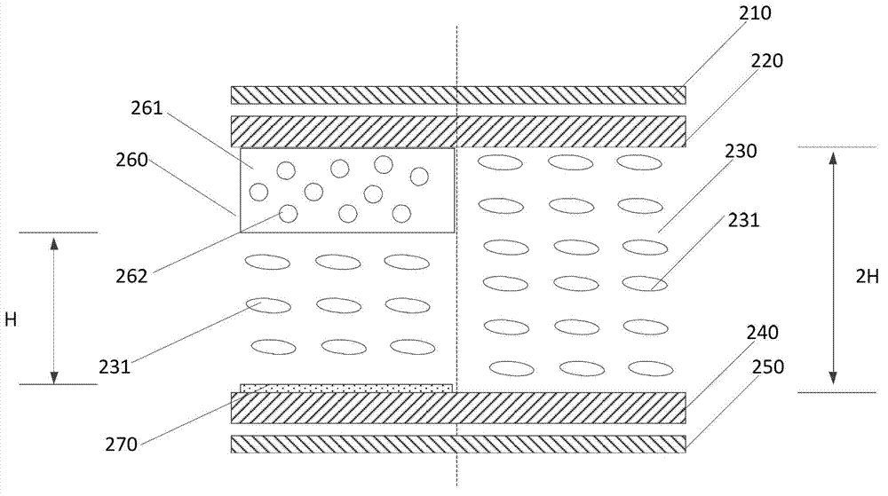
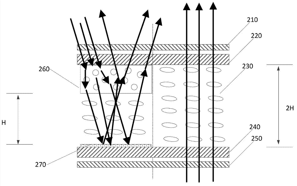
[0030] The transflective display panel of Embodiment 1 of the present invention is as follows figure 2 As shown, the transflective display panel includes: a reflection area (corresponding to figure 2 left of the dotted line) and the transmissive region (corresponding to figure 2 to the right of the dotted line).

[0031] Both the reflective area and the transmissive area include: an upper polarizer 210 , a color filter substrate 220 , a liquid crystal layer 230 , an array substrate 240 and a lower polarizer 250 . The liquid crystal layer 230 is arranged between the color filter substrate 220 and the array substrate 240, the upper polarizer 210 is arranged on the side of the color filter substrate 220 away from the liquid crystal layer 230, and the lower polarizer 250 It is disposed on the side of the array substrate 240 away from the liquid crystal layer 230 .

[0032] The reflective area further includes: a first reflective layer 270 disposed on the side of the array su...

Embodiment 2

[0044] Figure 4 It is the flow chart of the preparation method of the transflective and semi-reflective display panel described in Embodiment 2 of the present invention, such as Figure 4 As shown, the method includes:

[0045] 410: Form a first reflective layer on a partial area of ​​the array substrate.

[0046] Specifically, a partial area of ​​the array substrate corresponds to a reflection area of ​​the transflective display panel. The first reflective layer is generally made of aluminum or silver, which can be formed on a part of the array substrate by sputtering, photolithography and other processes.

[0047] 420: Form a diffuse reflection layer on a partial area of ​​the color filter substrate.

[0048] Specifically, a partial area of ​​the color filter substrate also corresponds to a reflection area of ​​the transflective display panel. The diffuse reflection layer can be made of a resin material mixed with nanoparticles, which can be formed on a part of the colo...

Embodiment 3

[0052] This embodiment provides a display device, which includes the transflective display panel described in Embodiment 1. The display device may be a liquid crystal television, a notebook computer, a tablet computer, a smart phone, and the like.

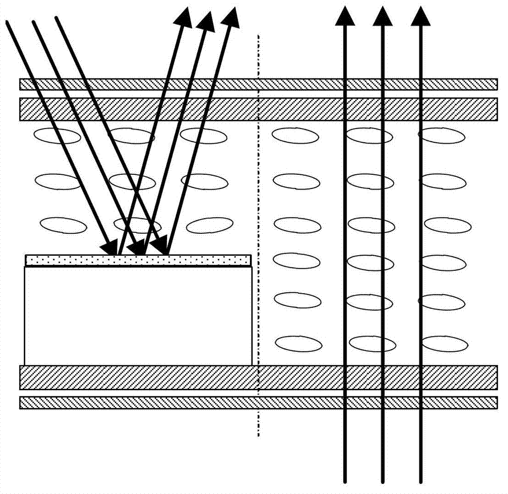
[0053] The transflective display panel, its manufacturing method, and display device described in the embodiments of the present invention, the reflective area includes: a first reflective layer disposed on the side of the array substrate close to the liquid crystal layer, and a first reflective layer disposed on the side of the array substrate The diffuse reflection layer on the side of the color filter substrate close to the liquid crystal layer, the diffuse reflection layer is opposite to the first reflection layer. Therefore, the angles of light reflected by the reflection area are diversified, the display viewing angle of the transflective display panel and the display device is significantly increased, and wide viewing angle ...


PUM

PropertyMeasurementUnit
whitenessaaaaaaaaaa

Abstract

The invention discloses a transflective display panel, a preparation method thereof and a display device and relates to the field of display. The transflective display panel comprises a reflection area and a transmission area. The reflection area comprises a color film substrate, an array substrate, a liquid crystal layer, a first reflection layer and a diffuse reflection layer, wherein the liquid crystal layer is arranged between the color film substrate and the array substrate, the first reflection layer is arranged on one side of the array substrate, which is close to the liquid crystal layer, the diffuse reflection layer is disposed on one side of the color film substrate, which is close to the liquid crystal layer, and the diffuse reflection layer and the first reflection layer are arranged oppositely. According to the transflective display panel, the preparation method thereof and the display device, display view angles of the transflective display panel and the display device are remarkably increased.

Description

technical field [0001] The invention relates to the field of liquid crystal display, in particular to a transflective display panel, a preparation method thereof, and a display device. Background technique [0002] The fully transparent display mode has excellent reading ability in low light or no light, but the brightness of the backlight is seriously insufficient in outdoor sunlight. Simply relying on increasing the brightness of the backlight will rapidly lose power, and the effect is also very unsatisfactory. Transflective LCDs can display images in both transmissive and reflective modes individually or simultaneously, so transflective LCDs can be used in any ambient light. [0003] Existing transflective liquid crystal panels such as figure 1 As shown, the left side of the dotted line in the figure is the reflective area of ​​the transflective liquid crystal panel, and the right side of the dotted line is the transmissive area. A reflective plate and a height cushion a...

Claims


Application Information

Patent Timeline
Patent Type & Authority Applications(China)
IPC IPC(8): G02F1/1335G02F1/1333
CPCG02F1/133504G02F1/133555G02F2202/36G02F2203/03G02F1/133565G02F1/133514
Inventor 王新星柳在健姚继开
Owner BOE TECH GRP CO LTD
Why Eureka
Try Eureka