Dragging type height-adjustable projector rack

A projector and pull-type technology, which is applied in the field of pull-type height-adjustable projector racks, can solve the problem that the projector cannot reach the projection height, and achieve the effects of simple structure, convenient assembly and portability

Inactive Publication Date: 2013-09-11
WUXI INST OF COMMERCE
View PDF12 Cites 3 Cited by
  • Summary
  • Abstract
  • Description
  • Claims
  • Application Information

AI Technical Summary

Problems solved by technology

Some problems are often encountered during this use. For example, because the tables and chairs are too short, the projector cannot reach the appropriate projection height when placed on the seat.

Method used


Image

  • Dragging type height-adjustable projector rack
  • Dragging type height-adjustable projector rack
  • Dragging type height-adjustable projector rack

Examples


Embodiment Construction

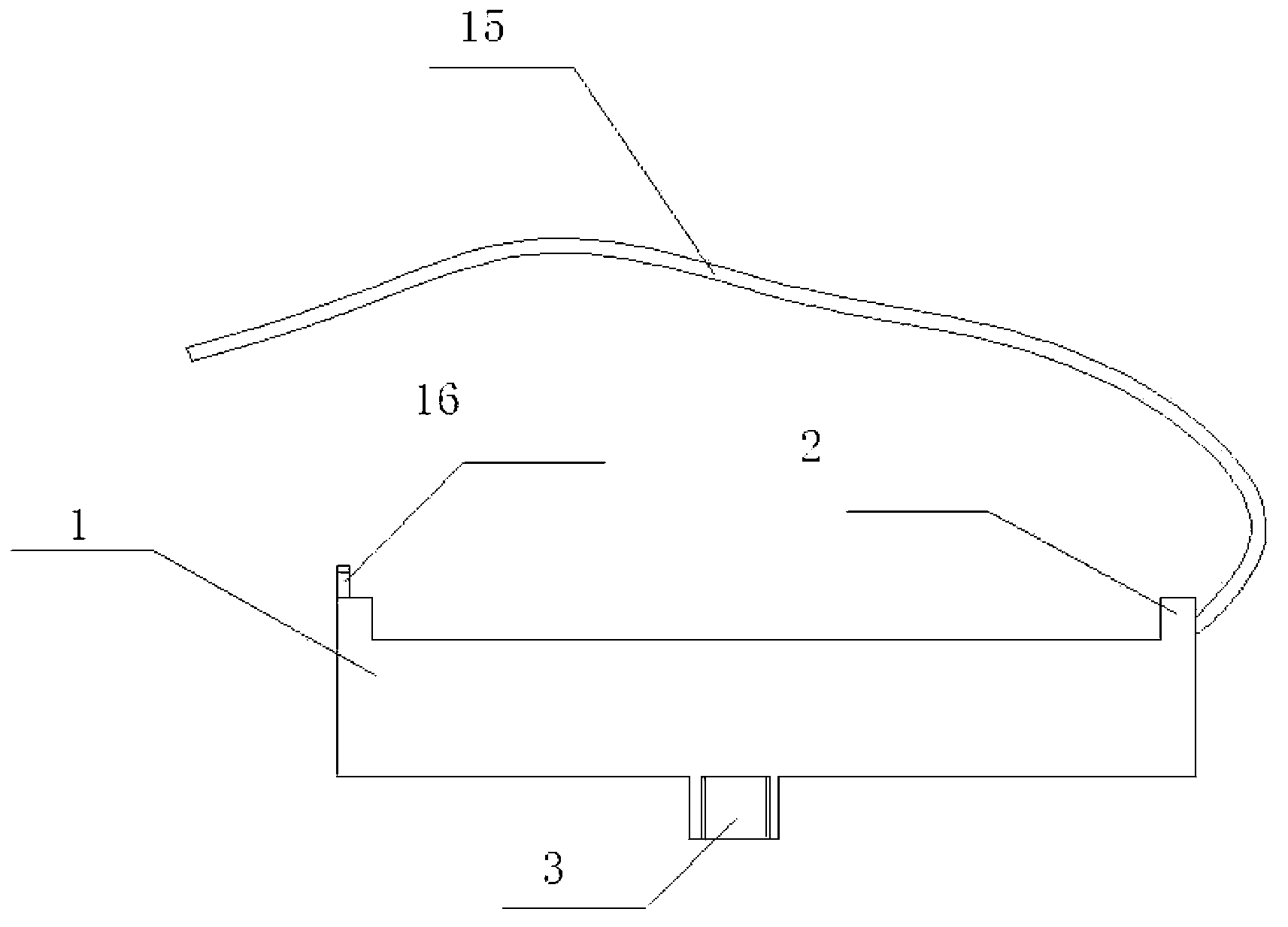
[0015] Such as Figure 1 to Figure 5 Shown is a pull-type height-adjustable projector stand, and an internally threaded boss 3 is provided in the middle of the bottom of the tray 1 . Flanges 2 are arranged around the upper surface of the tray 1 to prevent projectors, instruments, etc. from slipping. The flange 2 is fixed with a binding rope 15, and the opposite flange 2 is provided with a binding buckle 16, by which the projector, instruments, etc. can be firmly locked to prevent falling and damage.

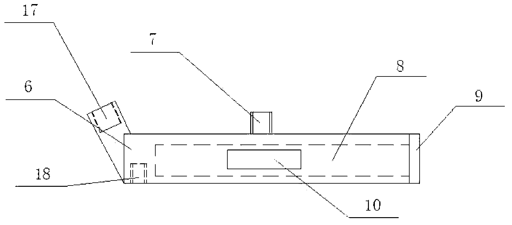
[0016] Base plate 6 is a cuboid, and the inside of base plate 6 is a rod storage case 8, and connecting rods and rollers can be stored in the rod storage case 8 inside base plate 6, and the side of base plate 6 is provided with box door 9. A threaded joint 7 is fixed on the upper surface of the bottom plate 6, and a detachable handle 10 is provided on the side. The bottom plate 6 is obliquely fixed with a pull column 17 relative to the other side of the box door 9 . Two thread...


PUM


Abstract

The invention discloses a dragging type height-adjustable projector rack which comprises a tray, a base plate and a connection rod. An upper connection rod of the connection rod is connected with boss threads arranged at the bottom of the tray, and a lower connection rod of the connection rod is connected with thread joints arranged on the base plate. The dragging type height-adjustable projector rack is convenient to carry and strong in adaptability, can randomly adjust the height of a projector as required, and facilitates teaching and display use.

Description

technical field [0001] The invention relates to a pull-type height-adjustable projector stand. Background technique [0002] Projectors are often used in teaching. Take the projector to the classroom before get out of class and connect it to the notebook, and put the projector away after class. Some problems are often encountered during this use. For example, because the tables and chairs are too short, the projector cannot reach the proper projection height when placed on the seat. Contents of the invention [0003] The object of the present invention is to provide a towable and height-adjustable projector stand aiming at the defects of the prior art. [0004] In order to achieve the above object, the present invention adopts the following technical scheme: a drag-type height-adjustable projector frame, including a tray, a bottom plate and a connecting rod, the upper connecting rod of the connecting rod is threadedly connected with the boss arranged at the bottom of the ...

Claims


Application Information

Patent Timeline
Patent Type & Authority Applications(China)
IPC IPC(8): G03B21/54F16M11/28F16M11/04F16M11/16
Inventor 崔伶玲
Owner WUXI INST OF COMMERCE
Why Eureka
Try Eureka