
Automatic switching method of battery pack

An automatic switching, battery pack technology, applied in terminal battery switching devices, secondary battery repair/maintenance, etc., can solve the problems of electric vehicles running out of power, small power battery capacity, shortening service life, etc., to extend the use time, extend the Service life, the effect of increasing compatibility

Active Publication Date: 2013-09-11
MICROVAST
View PDF3 Cites 14 Cited by
  • Summary
  • Abstract
  • Description
  • Claims
  • Application Information

AI Technical Summary

Problems solved by technology

However, there are still some problems in the current electric vehicles, which make it difficult to popularize quickly.
[0003] The capacity of the power battery of an electric vehicle is relatively small, and the driving distance per unit volume of the power battery is far inferior to that of a gasoline vehicle. If the driving distance is too long, it is easy to cause the electric vehicle to run out of power. Running for a long time in the undervoltage state will cause irreversible damage, reduce the service life, and increase the maintenance cost of electric vehicles in disguise. The traditional method is to install multiple battery packs in electric vehicles. When short-distance driving is required, only install A small number of modules such as one or two groups to reduce the weight of the body and save power; when it is necessary to drive for a long distance, more battery modules are installed, and after one group is used up, it can be switched to another group to extend the mileage
However, this working mode requires the user to manually switch the exhausted battery modules, which increases the complexity of the user

Method used


Image

  • Automatic switching method of battery pack
  • Automatic switching method of battery pack

Examples


Embodiment Construction

[0020] The present invention will be further described in detail below in conjunction with the accompanying drawings and embodiments.

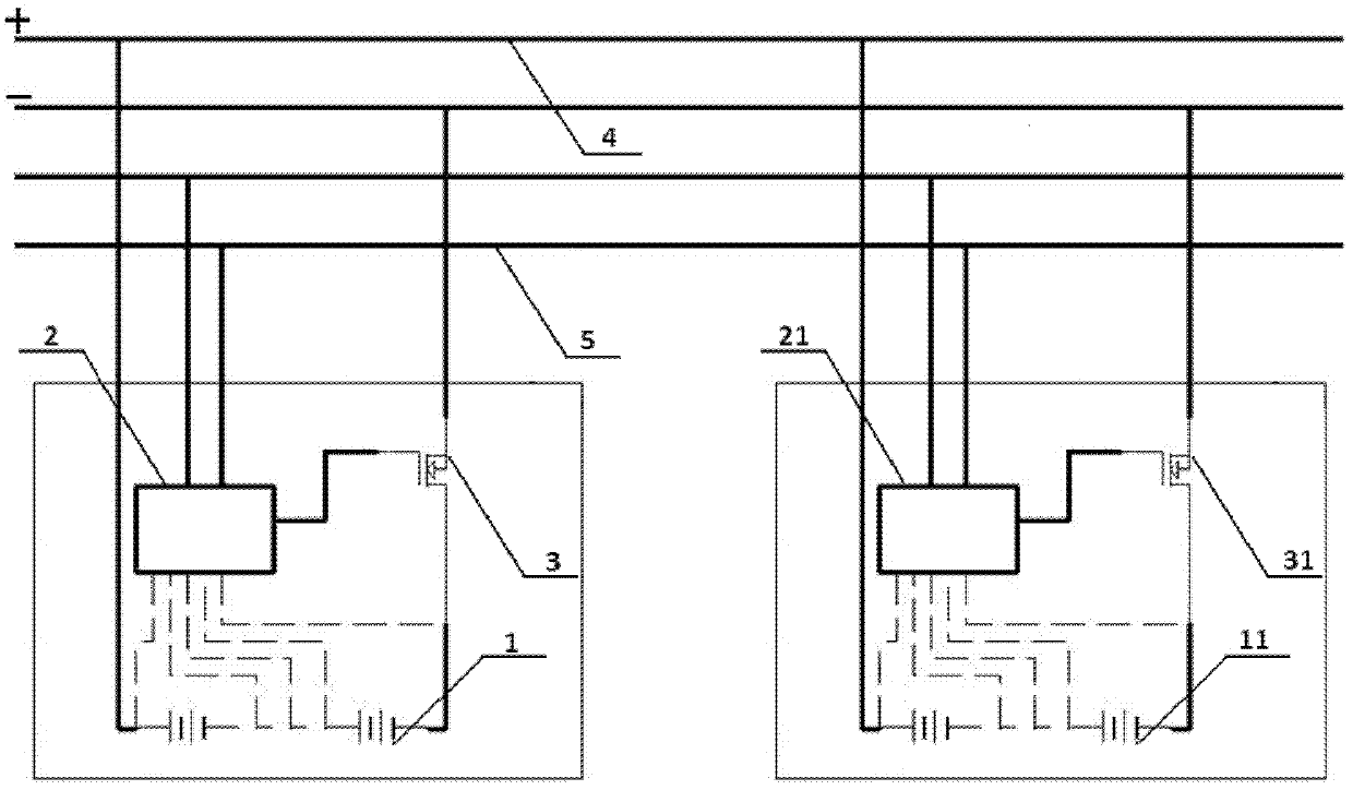
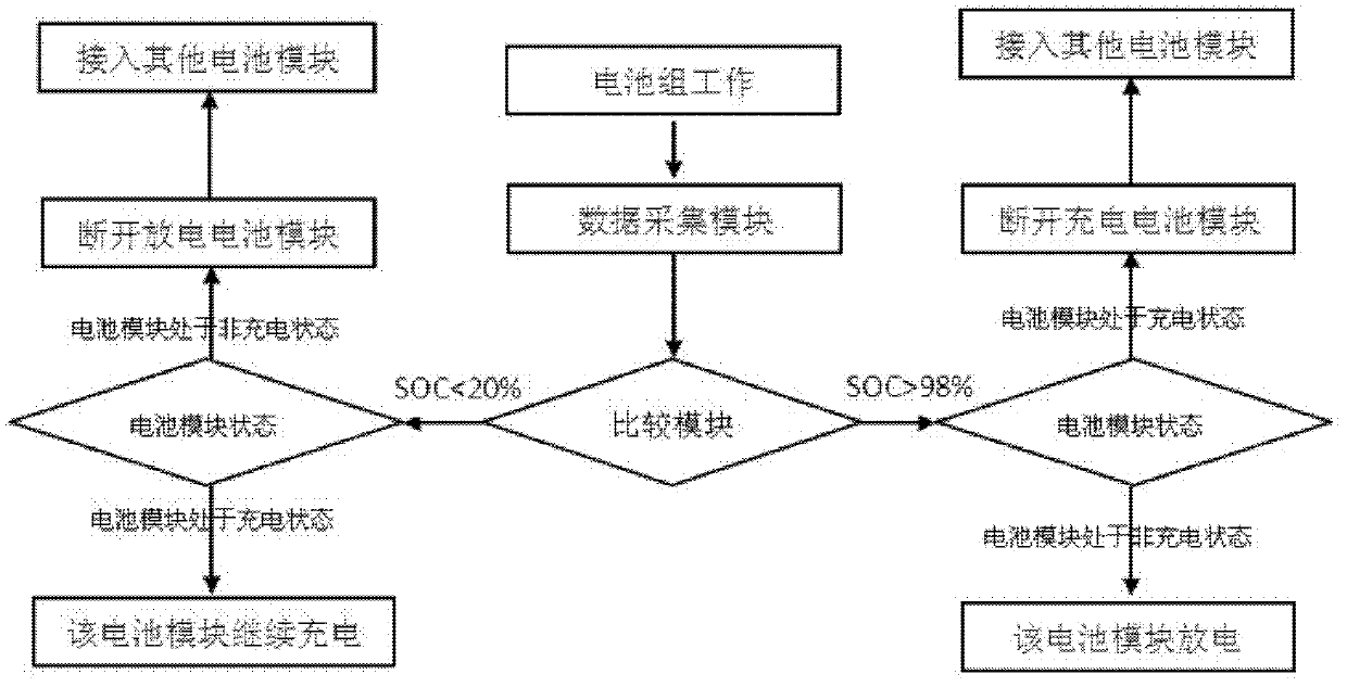
[0021] The present invention provides a method capable of automatically switching between several battery modules, including a battery module 1, a battery management system 2, and a switch 3. Each battery module 1 includes a battery management system 2 and a switch 3, and the battery module 1 passes through the switch 3. Connect the circuit bus 4. The battery management system 2 in each battery module 1 is connected to each other through the data bus 5. The battery management system 2 includes a data acquisition module for collecting information of the battery module 1, a data comparison module and a control module. The data comparison module A predetermined value is set and the information of the battery module 1 collected by the data acquisition module is compared with the predetermined value, and the control module controls the opening or cl...


PUM


Abstract

The invention provides an automatic switching method of a battery pack. The automatic switching method of the battery pack relates to a plurality of battery modules, each battery module comprises a battery management system and a switch, and battery units are connected with a circuit bus through the switches. The battery management systems of all the battery modules are connected mutually through data buses, and each battery management system comprises a data collection module collecting battery module information, a data comparison module and a control module. Preset values are set in the data comparison modules, the battery module information collected by the data collection modules is compared with the set preset values, and the control modules control switching off or switching on of the switches according to information of the data comparison modules. After the scheme is adopted, on the premise that a control system of an electric vehicle is not changed, the battery modules are used to supply power jointly, the requirement for consistency among all the modules does not exist, compatibility of the battery pack is improved, and meanwhile, the automatic switching method of the battery pack can avoid overcharging or over-discharging of the battery pack, prolong service life and save costs.

Description

technical field [0001] The invention relates to a battery pack switching method, in particular to an automatic switching method based on battery pack information. Background technique [0002] In recent years, the continuous rise of oil prices has affected the nerves of the world economy. Although the income of many people is enough to afford a gasoline car, the high oil price will greatly increase the daily expenses of car owners, and in serious cases will reduce the cost of car owners. People urgently need a cheap and economical new energy to replace traditional fuel. In the past few years, electric vehicles were only a concept, but after just a few years of development, some key technologies of power batteries have been broken through, and the safety performance, cycle life, and energy density of power batteries that people have criticized have been greatly improved. , the electric car, a means of transportation that completely gets rid of oil dependence, has quietly com...

Claims


Application Information

Patent Timeline
Patent Type & Authority Applications(China)
IPC IPC(8): H02J7/36H01M10/42
CPCY02E60/10
Inventor 毛伟良赵彪
Owner MICROVAST
Learn More