Cooler and cooling device
A cooler and cooling water technology, applied in cooling/ventilation/heating transformation, electrical solid state devices, semiconductor devices, etc., can solve the problem of large cooling water pressure loss and achieve the effect of small pressure loss and high heat exchange efficiency
- Summary
- Abstract
- Description
- Claims
- Application Information
AI Technical Summary
Problems solved by technology
Method used
Image

Examples
Embodiment approach 1
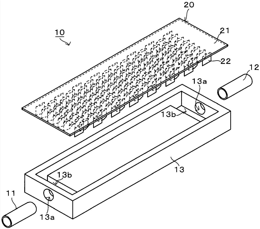
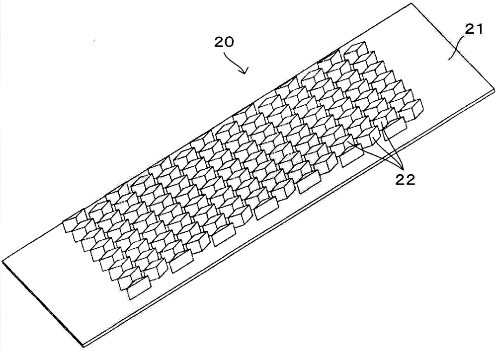
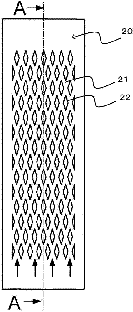
[0039] figure 1 It is a figure which shows the outline of the structure of the cooling device 10 concerning Embodiment 1 of this invention. The cooling device 10 according to the first embodiment of the present invention is used to cool, for example, electronic devices such as CPUs, LSIs, and inverters, and cooling objects such as power semiconductors. Cooling device 10 such as figure 1 As shown, the cooling water inlet 11, the outlet 12, the box 13, and the heat exchange unit (cooler) 20 are provided. In addition, the cooling device 10 includes a cooling water pressure feeding mechanism not shown, such as a pump driven by an electric motor. Below, the thick arrow in the figure indicates the flow of cooling water. In addition, in the cooling device 10, the cooling water may be circulated by a cooling water pressure feed mechanism. In this case, a storage tank and a filter may be provided in the circulating flow path. In addition, as cooling water, for example, water, LLC, al...
Embodiment approach 2
[0053] Picture 9 It is a figure which shows the outline of the structure of the cooling device 110 of Embodiment 2. In the cooling device 110 of the second embodiment, a laminate 30 is provided instead of the heat exchange unit 20 of the first embodiment. The laminated body 30 is constituted by stacking a plurality of flat plates (heat exchange flat plates) 31, is put in through the opening of the box body 13, is covered by the cover 14, and is arranged in the cooling water flow path. Hereinafter, description of the configuration common to Embodiment 1 will be omitted.
[0054] The plurality of flat plates 31 constituting the laminated body 30 are formed of materials with high thermal conductivity such as copper, aluminum, and iron. Each of the plurality of plates 31 such as Figure 9~Figure 11 As shown, it is formed in a plate shape with a rectangular plate surface, and a plurality of zigzag (zigzag) slits 32 penetrating in the thickness direction (stacking direction) are form...
Embodiment approach 3
[0059] Figure 14 It is a plan view of a laminated body 30A of Embodiment 3. Figure 15 as well as Figure 16 Yes Figure 14 C-C and D-D cross-sectional views. In the third embodiment, similar to the second embodiment, the flat plates 31 formed with a plurality of zigzag slits 32 are laminated to form a laminated body 30A. However, the laminated flat plates 31 include slits in the direction of the cooling water flow path. 32 long flat plates 31A and short flat plates 31B. Such as Figure 14 ~ Figure 16 As shown, if the positions of the slits 32 are shifted to form the laminated body 30A, the contact area of the cooling water and the laminated body 30A can be increased, the cooling water can be moved in the stacking direction, and the heat exchange efficiency of the cooling device can be improved. Here, although this effect can be easily obtained by increasing the amount by which the slits 32 are shifted from each other, if the space in which the slits 32 communicate with eac...
PUM
 Abstract
Description
Claims
Application Information
 - R&D Engineer
- R&D Manager
- IP Professional
- Industry Leading Data Capabilities
- Powerful AI technology
- Patent DNA Extraction
Browse by: Latest US Patents, China's latest patents, Technical Efficacy Thesaurus, Application Domain, Technology Topic.
© 2024 PatSnap. All rights reserved.Legal|Privacy policy|Modern Slavery Act Transparency Statement|Sitemap