

Tunneling machine
A technology of tunnel boring machine and traveling mechanism, applied in tunnels, cutting machinery, mining equipment, etc., can solve the problems of incompatibility, large structure height, etc.
- Summary
- Abstract
- Description
- Claims
- Application Information
AI Technical Summary
Problems solved by technology
Method used
Image

Examples
Embodiment Construction
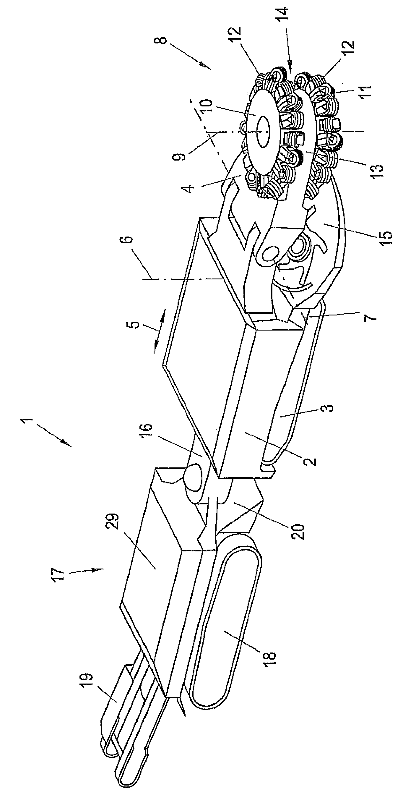
[0024] exist figure 1 shows a tunnel boring machine 1 having a base frame 2 with a crawler 3 . The boom is indicated at 4 and is guided on the base frame 2 so as to be movable in the machine longitudinal direction corresponding to the double arrow 5 . The boom 4 can be mounted pivotally about a vertical axis 6 by means of a horizontal pivot mechanism not shown further.
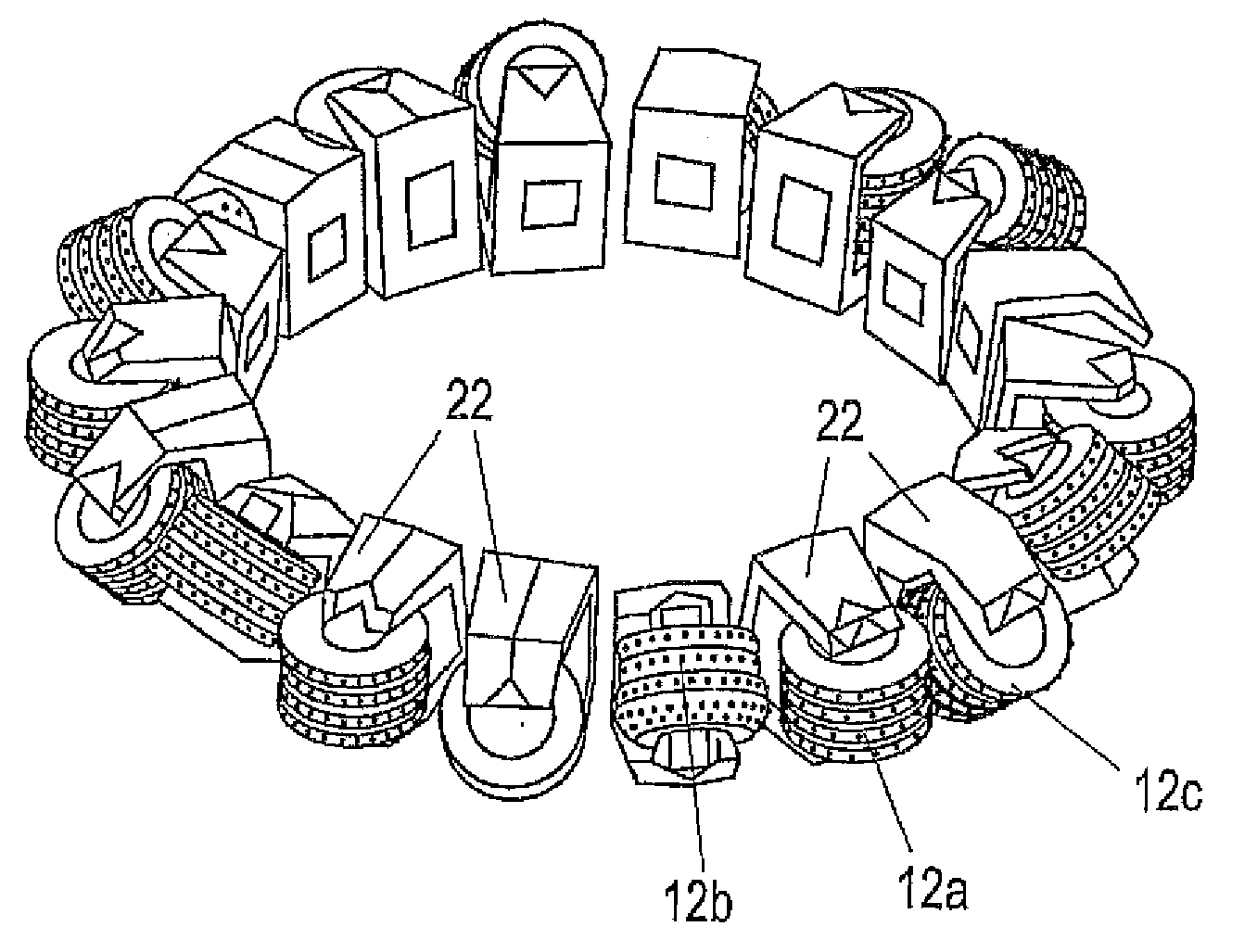
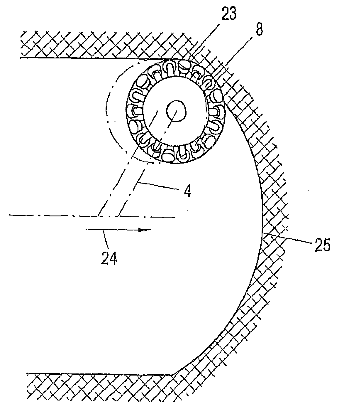
[0025]The front section of the boom 4 can be supported pivotally about a horizontal axis 7 by means of a vertical pivot mechanism not further shown. In this way, the boom 4 can be pivoted relative to the base frame 2 both horizontally and vertically. The cutting device 8 is mounted on the boom 4 so as to be rotatable about a pivot axis 9 , wherein a rotary drive (not further shown) drives the cutting device 8 for rotation about the axis 9 . The cutting device 8 has two tool holders 10 and 11 which each have a plurality of cutting tools 12 on their periphery. The following will also be based on image 3 an...
PUM
 Abstract
Description
Claims
Application Information