Vibration element, optical scanning device, and image forming device and image projecting device using the optical scanning device

A technology of optical scanning device and vibrating element, which is applied in electromechanical devices, projection devices, electrical components, etc., can solve problems such as inability to scan, abnormal vibration, etc., and achieve the effects of improving flatness, suppressing deterioration, and accurately positioning magnets

Active Publication Date: 2015-11-25
CANON DENSHI KK
View PDF7 Cites 0 Cited by
  • Summary
  • Abstract
  • Description
  • Claims
  • Application Information

AI Technical Summary

Problems solved by technology

However, since the common center of gravity between the fixed member and the magnet engaged with the fixed member is away from the central axis of the torsion bar, the light reflecting surface formed on the surface of the magnet sometimes vibrates abnormally, thereby making it impossible to direct the light to the desired direction. to scan

Method used


Image

  • Vibration element, optical scanning device, and image forming device and image projecting device using the optical scanning device
  • Vibration element, optical scanning device, and image forming device and image projecting device using the optical scanning device
  • Vibration element, optical scanning device, and image forming device and image projecting device using the optical scanning device

Examples


Embodiment Construction

[0081] Below, refer to Figure 1 to Figure 10 An embodiment in which the image forming apparatus of the present invention is applied to a laser beam printer (hereinafter referred to as LBP) will be described in detail. However, it should be noted that the present invention is not limited to such embodiments, but can further combine the structures of different embodiments or appropriately adopt other arbitrary structures described in the claims and belonging to the technical gist of the present invention as required. structure.

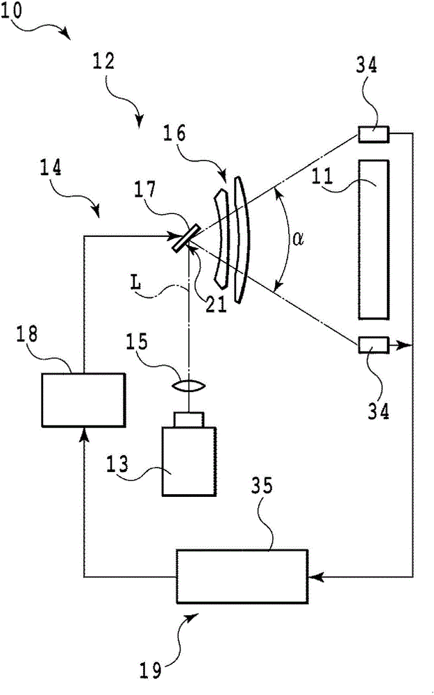
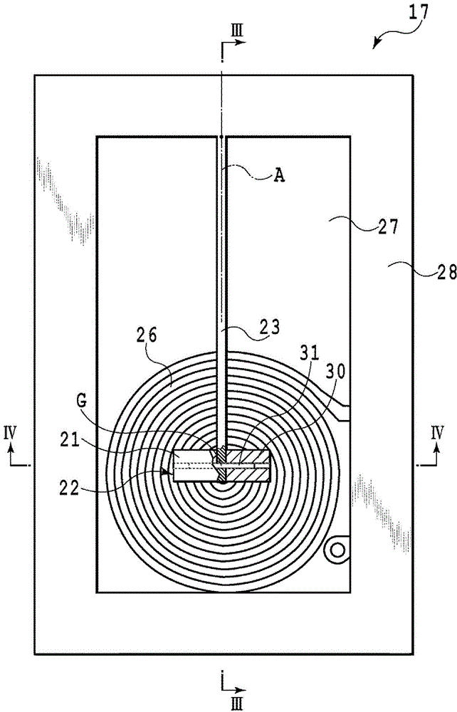
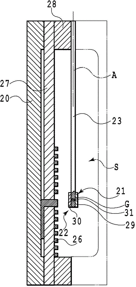
[0082] The exposure part of the LBP of this embodiment is schematically shown in figure 1 In , the main part of the vibrating element in the optical scanning device of the LBP is extracted and shown in figure 2 in, will figure 2 The shape of the III-III cross-section in image 3 in, will figure 2 The enlarged cross-sectional shape of IV-IV in Figure 4 middle. And, the main part of the vibrating element is shown in the disassembled state in ...


PUM

PropertyMeasurementUnit
surface smoothnessaaaaaaaaaa
diameteraaaaaaaaaa

Abstract

The oscillation element according to the present invention includes a torsion bar mounted on a base, and an oscillating member having a light reflection surface for reflecting light from a light source, which is fixed on the torsion bar protruding from the base. The oscillating member oscillates about a longitudinal axis of the torsion bar with an elastic deformation of the torsion bar, thereby deflecting the light that reflects at the light reflection surface in a direction intersecting the longitudinal axis. The oscillating member has two plates that are joined together so as to sandwich the torsion bar. On joining surfaces of the plates are provided with grooves for receiving the torsion bar, respectively. The plates have a symmetrical shape that the longitudinal axis serves as the axis of symmetry.

Description

technical field [0001] The present invention relates to a vibrating element and an optical scanning device utilizing resonance of a torsion bar, and an image forming device and an image projection device incorporating the optical scanning device. Background technique [0002] Patent Document 1, Patent Document 2, etc. propose an optical scanning device that uses resonance of an oscillating system to oscillate the mirror at high speed in place of a rotating mirror such as a polygon mirror used in an optical scanner, thereby allowing light to travel. scanning. Patent Document 3 also proposes a oscillating body device, a potential sensor, and the like having the same principle. [0003] Generally, such an optical scanning element as a vibrating element for constituting an optical scanning device or a potential sensor includes: a plate-shaped oscillating body; a torsion bar for fixing the oscillating body; The body swings around the lengthwise axis of the torsion bar. In addi...

Claims


Application Information

Patent Timeline
Patent Type & Authority Patents(China)
IPC IPC(8): H02K33/16G02B26/10H04N1/113
CPCH02K33/00B41J2/44B41J2/471G02B7/1821G02B26/10G02B26/105G03B21/28H02K15/00H02K33/16H04N1/1135Y10T29/49009
Inventor 若林孝幸铃木成己新井克美周耀民
Owner CANON DENSHI KK
Why Eureka
Try Eureka