Device for measuring optical performance of material under strong laser condition

A technology of optical performance and measuring device, which is applied in the direction of measuring device, scattering characteristic measurement, material analysis by optical means, etc., can solve the problems of anti-laser ability test of materials that cannot be damaged by high-energy lasers, and achieves reduction in volume and mechanical The effect of vibration, the effect of strong expansion

Inactive Publication Date: 2015-06-03
BEIJING INSTITUTE OF TECHNOLOGYGY
View PDF3 Cites 0 Cited by
  • Summary
  • Abstract
  • Description
  • Claims
  • Application Information

AI Technical Summary

Problems solved by technology

[0003] At the same time, because the traditional measurement devices for optical properties of materials are all measured under low-power laser conditions, they can only test the transmittance, absorption rate and other properties of materials, and cannot conduct research on the damage mechanism of high-energy lasers and test the anti-laser ability of materials.

Method used


Image

  • Device for measuring optical performance of material under strong laser condition
  • Device for measuring optical performance of material under strong laser condition
  • Device for measuring optical performance of material under strong laser condition

Examples


Embodiment 1

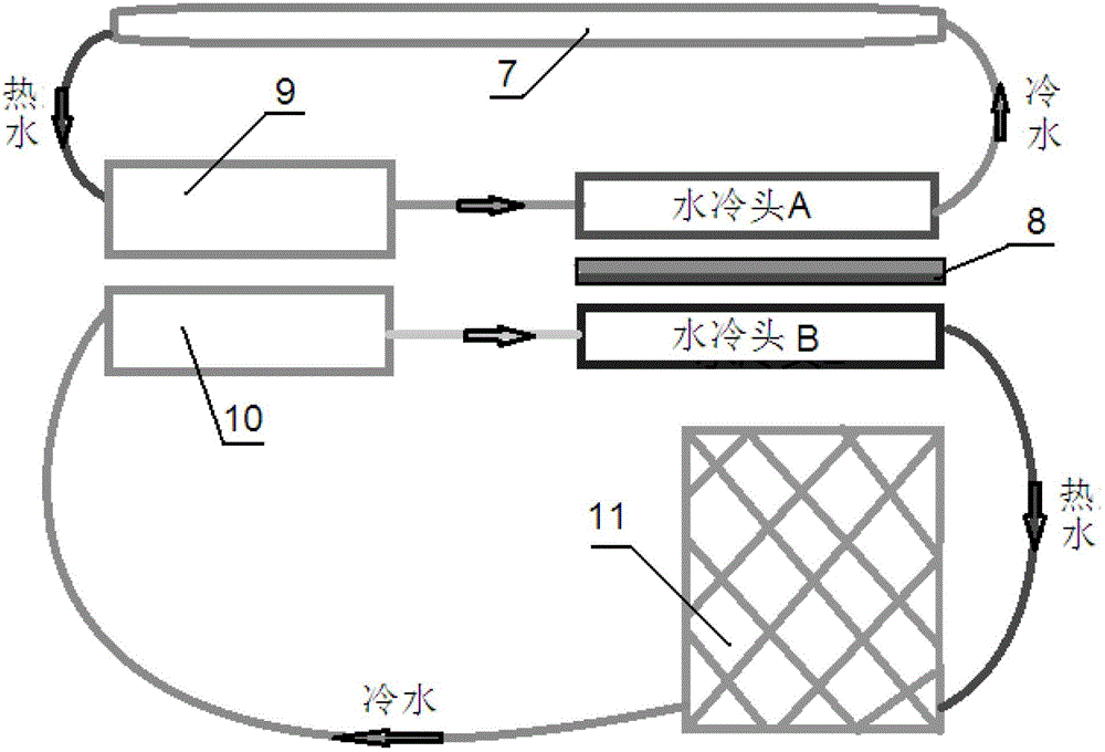
[0036] The cooling device includes a laser circulating water tank 9, a radiator circulating water tank 10, a heat exchanger 11, a semiconductor cooling chip and two water cooling heads (water cooling head A and water cooling head B respectively). The cooling end of the semiconductor refrigerating sheet is attached to the water cooling head A, and the heating end is attached to the water cooling head B. CO 2 The water inlet end of the laser tube 7 is connected to the water cooling head A, and the water outlet end is connected to the water cooling head A through the laser circulating water tank 9 . The water inlet end of the heat exchanger 11 is connected to the water cooling head B, and the water outlet end is connected to the water cooling head B through the radiator circulating water tank 10 . In this embodiment, the heat exchanger adopts an air-cooled heat exchanger to realize heat exchange between water and air. A fan is installed in the air-cooled heat exchanger, and the ...

Embodiment 2

[0039] In this embodiment, the refrigerating capacity of the cooling device is controllable through three water cooling heads, four semiconductor refrigerating plates, three temperature sensors 12, a temperature controller and two electromagnetic relays, so as to achieve the purpose of artificially controlling the refrigerating capacity. Its structural diagram is as Figure 4 As shown, the three water cooling heads are respectively water cooling head A, water cooling head B and water cooling head C; two of the four semiconductor cooling chips are connected in parallel to form two semiconductor cooling chip groups, and one semiconductor cooling chip group is installed on Between water-cooling head A and water-cooling head B, wherein water-cooling head A is attached to the heating end of the semiconductor cooling chip group, and water-cooling head B is attached to the cooling end of the semiconductor cooling chip group; another semiconductor cooling chip group is installed on the...


PUM


Abstract

The invention discloses a device for measuring the optical performance of a material under a strong laser condition, which can be used for testing the transmissivity and the reflectivity of the material under the strong laser condition, and can also be used for carrying out researches on a high-energy laser damage mechanism and anti-laser capability test on the material. The measurement device comprises an evaluation part and a cooling device, wherein the evaluation part comprises an infrared generation device, a sealing index plate and a light power detection device; a CO2 laser tube with output power which is more than 40W is used as the infrared generation device; the sealing index plate is internally provided with a rotatable sample supporting disc and a supporting rotary disc; a detection head of the light power detection device is fixed on the supporting rotary disc; a sample of a material to be detected is fixed on the sample supporting disc; accurate measurement on relative rotary angles of the sample supporting disc and the supporting rotary disc is carried out by a dial. Meanwhile, a semiconductor chilling plate is used for chilling the CO2 laser tube; the chilling amount of the cooling device is controllable through a temperature sensor, a temperature controller and an electromagnetic relay; a laser device is maintained at an optimal working state.

Description

technical field [0001] The invention relates to a measuring device, in particular to a device for measuring optical properties of materials under strong laser conditions. Background technique [0002] At present, domestic test materials use laser spectrum analyzers, laser spectrophotometers, etc. for the properties of laser transmittance, reflectivity, and absorptivity. The power is only at the milliwatt level. and absorbent equipment. The high-power laser refers to a laser with a power greater than 40W. [0003] At the same time, because the traditional measurement devices for optical properties of materials are all measured under low-power laser conditions, they can only test the transmittance, absorption rate and other properties of the material, and cannot conduct research on the damage mechanism of high-energy lasers and test the anti-laser ability of materials. Contents of the invention [0004] In view of this, the present invention provides a device for measuring...

Claims


Application Information

Patent Timeline
Patent Type & Authority Patents(China)
IPC IPC(8): G01N21/47G01N21/59G01N21/17
Inventor 金海波张家嵩李静波于堃
Owner BEIJING INSTITUTE OF TECHNOLOGYGY
Why Eureka
Try Eureka