Auto-control and auto-detection system for non-decoupled dynamic compaction machine

A technology of automatic detection and dynamic compaction machine, applied in the direction of electrical program control, program control in sequence/logic controller, etc.

Inactive Publication Date: 2013-09-18
SHANDONG UNIV OF SCI & TECH +1
View PDF7 Cites 11 Cited by
  • Summary
  • Abstract
  • Description
  • Claims
  • Application Information

AI Technical Summary

Problems solved by technology

[0003] 1. The heavy hammer needs to be hooked manually every time it is unhooked. The labor intensity of the workers is high and there are potential safety hazards
[0004] 2. If the inspector enters the ramming pit to detect the amount of ramming, there will be inaccurate detection and potential safety hazards; if the inspector uses a laser rangefinder or an acoustic rangefinder For testing, the equipment must be set up every time, and then removed after the test, which is troublesome and labor-intensive
If an online test system is used for detection, the system detects the deformation of the main arm of the dynamic tamping arm in real time during the tamping process and outputs a step signal to the programmable controller accordingly, and the programmable controller according to the step It is also too troublesome and costly to control the ramming depth test unit to carry out the depth test according to the signal
[0005] 3. The heavy hammer decoupling has limitations when compacting shallow water, silt and other terrains. After the heavy hammer enters the water and silt, the workers cannot hook
[0006] 4. When the rammer is lifted to the top, it is easy to overwind and bite the rope

Method used


Image

  • Auto-control and auto-detection system for non-decoupled dynamic compaction machine

Examples


Embodiment Construction

[0021] The present invention is described in detail below in conjunction with accompanying drawing and specific embodiment:

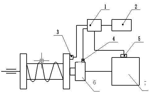
[0022] Such as figure 1 As shown, the automatic control and automatic detection system of the non-decoupling dynamic compaction machine: includes a programmable controller PLC1, a shaft encoder 3, a pressure sensor 4, an electromagnetic reversing valve 5 and a touch screen 2, and the input end of the shaft encoder 3 It is connected to the motor 6 shaft, the input end of the pressure sensor 4 is connected to the motor 6, the input end of the electromagnetic reversing valve 5 is connected to the hydraulic station 7 of the dynamic compaction machine, and the input end of the programmable controller PLC1 is connected to the shaft The output ends of the encoder 3 , the pressure sensor 4 , and the electromagnetic reversing valve 5 are respectively connected, and the output end of the programmable controller PLC1 is connected with the touch screen 2 .

[002...


PUM


Abstract

The invention discloses an auto-control and auto-detection system for a non-decoupled dynamic compaction machine and relates to the field of dynamic compaction machinery. The system comprises a PLC (programmable logic controller) (1), an axial encoder (3), a pressure sensor (4), a solenoid reversing valve (5) and a touch screen (2). The input end of the axial encoder (3) is connected with a motor (6) through a shaft. The input end of the pressure sensor (4) is connected with the motor (6). The input end of the solenoid reversing valve (5) is connected with a dynamic compaction machine hydraulic station (7). The input end of the PLC is connected with the output end of each of the axial encoder (3), the pressure sensor (4) and the solenoid reversing valve (5). The output end of the PLC (1) is connected with the touch screen (2). The auto-control and auto-detection system for the non-decoupled dynamic compaction machine has the advantages that a rammer is not decoupled, convenience and quickness are provided, ramming volume can be automatically and precisely detected, the touch screen is available for real-time monitoring, debugging is simple and the system is high in cost performance. The auto-control and auto-detection system for the non-decoupled dynamic compaction machine is applicable to various dynamic compaction devices.

Description

technical field [0001] The invention relates to the field of dynamic tamping machines, in particular to an automatic control and automatic detection system for a dynamic tamping machine without decoupling of the heavy hammer. Background technique [0002] The dynamic compaction machine is one of the indispensable large-scale equipment for modern compaction bases, which is used to improve the strength of the foundation, reduce compressibility, and eliminate collapsibility. The dynamic compaction machine has the following problems in the working process: [0003] 1. The heavy hammer needs to be hooked manually every time it is unhooked. The labor intensity of the workers is high and there are potential safety hazards. [0004] 2. If the inspectors enter the ramming pit to detect the amount of tamping, there will be inaccurate detection and potential safety hazards; if the inspectors use laser rangefinders and sonic rangefinders to detect, they must set up equipment every t...

Claims


Application Information

Patent Timeline
Patent Type & Authority Applications(China)
IPC IPC(8): G05B19/05
Inventor 宋若峰杨崇庆杨永腾刘悦龙王刚赵磊王新潜刘洋
Owner SHANDONG UNIV OF SCI & TECH
Why Eureka
Try Eureka