Laminating mechanism of storage battery wrapping and laminating machine

A stacking machine and storage battery technology, which is applied in secondary battery manufacturing, sustainable manufacturing/processing, climate sustainability, etc., can solve the problems of health impact of operators, increased structural complexity, and low quality of packaging. To achieve the effect of compact structure, less space occupation, firm and stable structure

Active Publication Date: 2013-09-18
ZHEJIANG HAIYUE AUTOMATIC MACHINERY
View PDF2 Cites 1 Cited by
  • Summary
  • Abstract
  • Description
  • Claims
  • Application Information

AI Technical Summary

Problems solved by technology

However, in the traditional "wrapping" process, manual operations are mostly used. The operator first takes a piece of negative plate, wraps the two sides of the positive plate with the cut separator paper, and then stacks the positive plate on the negative plate after wrapping. On the other hand, ensure that there is separator paper between each group of positive and negative plates, and repeat the above operations in a cycle to complete the wrapping and assembly of the plates. Dust can also affect the health of operating workers
[0003] The stacking mechanism of the existing automatic package sheet stacking machine is a liftable pallet, and the pallet is set under the negative plate material table, and the negative plate and the package are alternately stacked on the pallet during the process of descending the pallet. One piece of positive plate to realize the stacking process of the battery, but in order to transfer the stacked electrode group out, it is necessary to set up a matching output device, which increases the complexity of the structure, and the pallet moves with the elevator in order to ensure Stability, so the speed is generally slow, and the pallet needs to recover, so the efficiency is low

Method used


Image

  • Laminating mechanism of storage battery wrapping and laminating machine
  • Laminating mechanism of storage battery wrapping and laminating machine
  • Laminating mechanism of storage battery wrapping and laminating machine

Examples


Embodiment 1

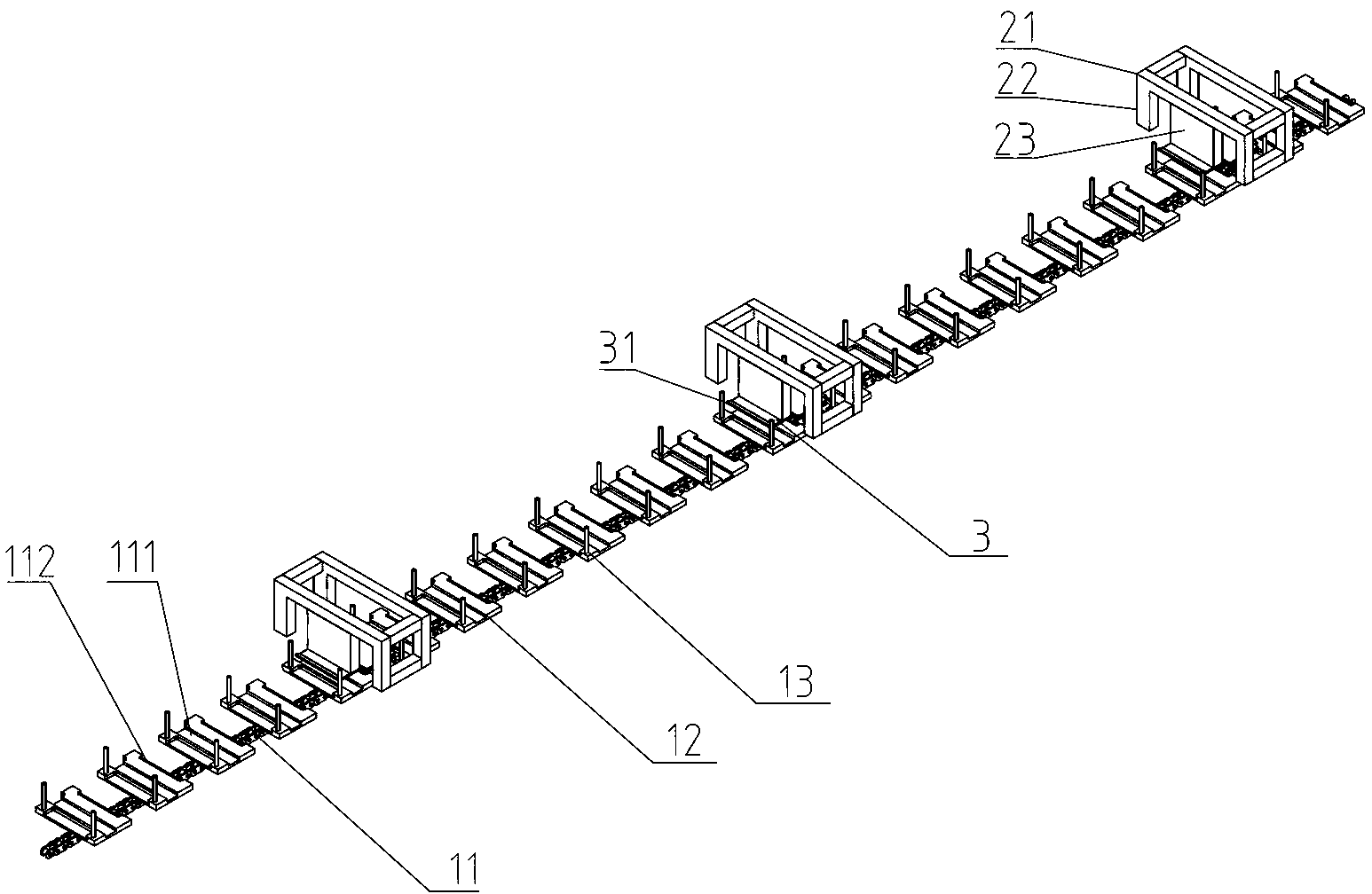
[0030] refer to figure 1 , the shown fixing frame 2 is provided with a fixing plate 23 extending downward to directly above the conveying device 1, and a supporting plate 3 is arranged at the bottom of the fixing plate 23, and the supporting plate 3 is volleyed above the conveying device 1 in this way, and the structure is simple and compact , maintenance and replacement are also convenient, and the fixed connection between the supporting plate 3 and the fixed plate 23 can improve the load-bearing capacity of the supporting plate 3.

[0031] The fixed frame 2 in the present embodiment comprises a top frame 21 and a column 22, and the column 22 is fixed on the frame 7 of the sheet stacker, and the fixed plate 23 is arranged on the top frame 21, between the column 22 and the frame 7 and The fixing plate 23 and the top frame 21 may be screwed or welded, and the structure of the fixed connection is firm. figure 1 The top frame 21 and the uprights 22 are shown as an integral struc...

Embodiment 2

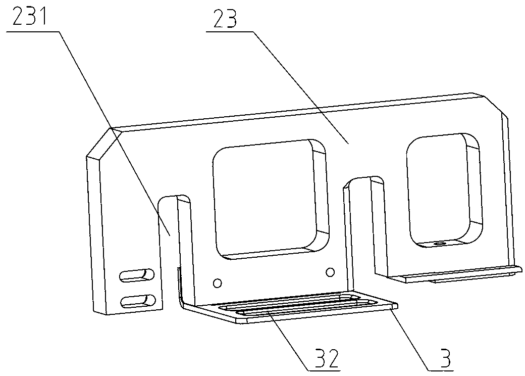
[0034] refer to figure 1 and figure 2 , another structural form of the fixing frame 2 , the fixing frame 2 only includes a fixing plate 23 arranged laterally along the conveying device 1 , and a supporting plate 3 is arranged at the bottom end of the fixing plate 23 .

[0035] In this embodiment, the end of the fixed plate 23 is fixedly connected to the frame 7 of the sheet stacker. The fixed plate 23 is provided with an avoidance groove 231. When the push rod 13 moves with the conveying device 1, it passes through the avoidance groove 231. . It can be welded or screwed between the fixed plate 23 and the frame 7 . Compared with Embodiment 1, the structure is simpler and the cost is relatively lower under the premise of completing the same function.

[0036] The conveying device 1 of the above-mentioned embodiment comprises a conveying chain 11, and the conveying chain 11 is provided with pallets 12 at intervals, and the conveying chain 11 can reciprocate. The boards are c...


PUM


Abstract

The invention discloses a laminating mechanism of a storage battery wrapping and laminating machine and relates to storage battery automatic production equipment. The conventional storage battery wrapping and laminating machine is low in laminating efficiency. The laminating mechanism disclosed by the invention comprises a conveying device and a plurality of carrying plates, wherein the carrying plates are arranged above the conveying device at intervals, are fixed above the conveying device through a fixing frame and are gradually heightened along the conveying direction of the conveying device; a push rod is arranged on the conveying device; the height of the push rod is greater than that of each carrying plate; when the conveying device runs, the push rod scraps polar plates on the carrying plates into the conveying device, and the polar plates are laminated on the conveying device layer by layer; base plates and wrapping polar plates of a base plate transferring device and a wrapping device are simultaneously transferred to the carrying plates of the fixing frame; in a running process of the conveying device, the polar plates on the carrying plates are continuously scraped into the conveying device; the polar plates are laminated on the conveying device to form plate groups and then are conveyed by the conveying device; and the plate groups can be continuously formed, so that the production efficiency is high.

Description

【Technical field】 [0001] The invention relates to an automatic production equipment for storage batteries, in particular to a stacking mechanism for a battery pack stacking machine. 【Background technique】 [0002] In the battery production process, there is a process of assembling the positive plate, negative plate, and separator paper into an electrode group. The separator paper is sandwiched between the positive plate and the negative plate, so it is usually called "wrapped sheet" in the industry. Or "pack board" process. However, in the traditional "wrapping" process, manual operations are mostly used. The operator first takes a piece of negative plate, wraps the two sides of the positive plate with the cut separator paper, and then stacks the positive plate on the negative plate after wrapping. On the other hand, ensure that there is separator paper between each group of positive and negative plates, and repeat the above operations in a cycle to complete the wrapping an...

Claims


Application Information

Patent Timeline
Patent Type & Authority Applications(China)
IPC IPC(8): H01M10/04
CPCY02E60/10Y02P70/50
Inventor 林雁斌张建章倪燮逵周富成费明儿黄亮亮李瑞陈义忠张勇根
Owner ZHEJIANG HAIYUE AUTOMATIC MACHINERY
Why Eureka
Try Eureka