Motor structure provided with resolver

A resolver and motor technology, which is applied in the direction of structural connection, casing/housing/support, electrical components, etc., can solve the problems of low motor load, complicated structure composition, and unsatisfactory structure, so as to expand the distance and reduce interference degree, the effect of preventing interference

Inactive Publication Date: 2013-09-18
HIWIN MIKROSYST
View PDF4 Cites 3 Cited by
  • Summary
  • Abstract
  • Description
  • Claims
  • Application Information

AI Technical Summary

Problems solved by technology

However, both the motor and the resolver use electric energy as their power source, and use the change of the magnetic field to convert the electric energy into mechanical energy to generate power, or sense the change of the magnetic field to generate a corresponding amplitude modulation signal, and the above is The technical content of synchronously analyzing the rotation angle position of the motor and connecting the resolver to the rotating motor in series can achieve the purpose of synchronous analysis, but the derived result is that the accuracy of the analysis is vulnerable to electromagnetic interference (Electromagnetic Interference), especially For resolvers with higher resolution requirements, the interference caused by the voltage generated by the interlinkage between the magnetic field and the conductor will be more significant
[0003] Specifically, in U.S. Patent No. 6,856,061, the specific technical content of setting the resolver between the inside of the shaft and the body of the internal-rotating direct-drive motor is disclosed. It is required that the angle resolver and the motor shaft rotate synchronously to obtain synchronous angular position information, but its structure is still not ideal, especially in avoiding the interference caused by the motor to the angle resolver. The US patent precedent Due to the too short distance between the resolver and the motor, there will be relatively large interference, and both the US patent record and the conventional technology have a relatively complicated structure. At the same time, due to these technical contents, the load that the motor can bear in the axial direction is low, which will affect its use effect, which will be more obvious for direct drive motors

Method used


Image

  • Motor structure provided with resolver
  • Motor structure provided with resolver
  • Motor structure provided with resolver

Examples


Embodiment Construction

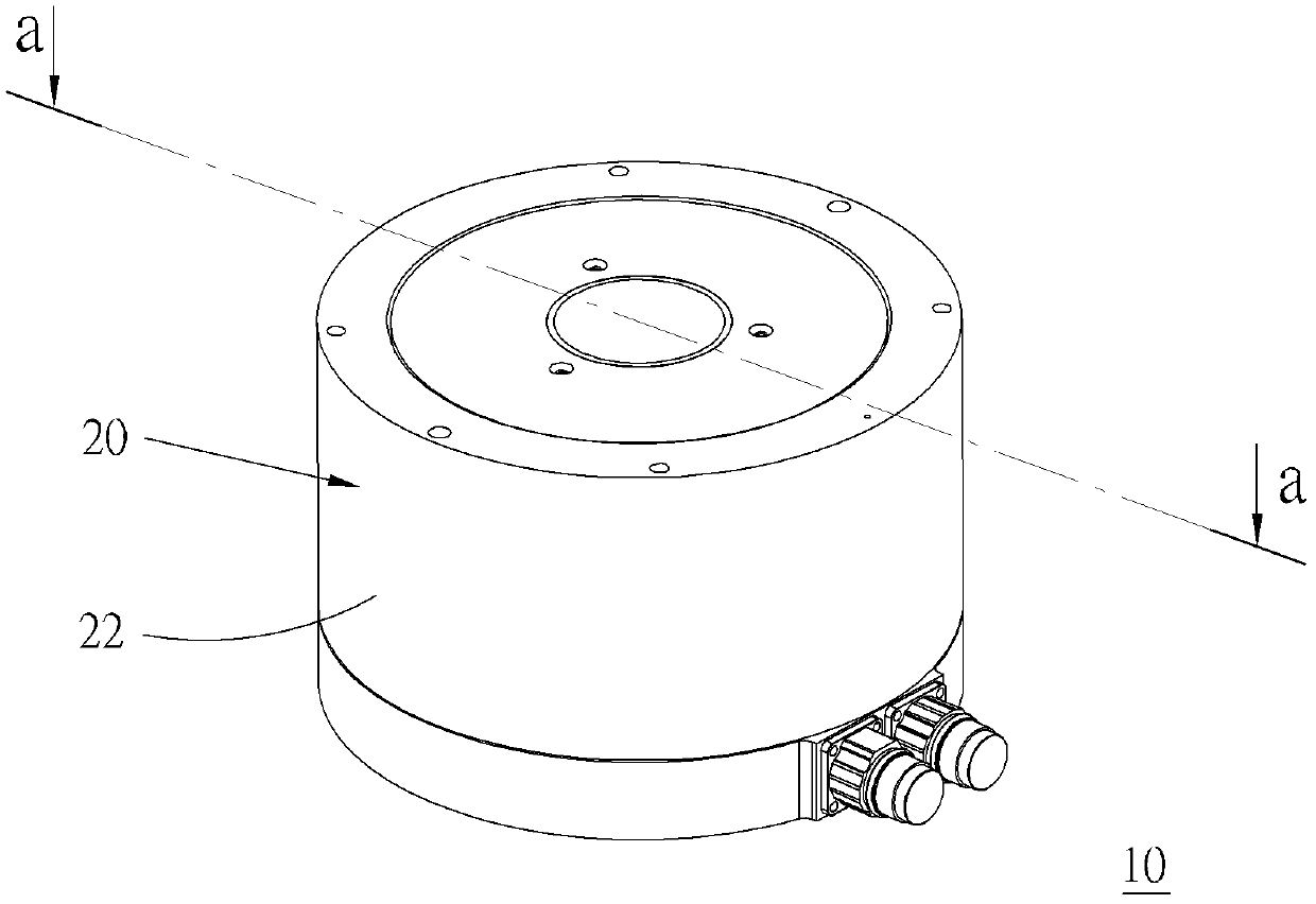
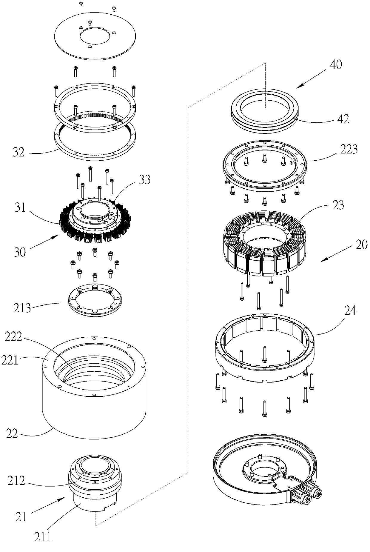
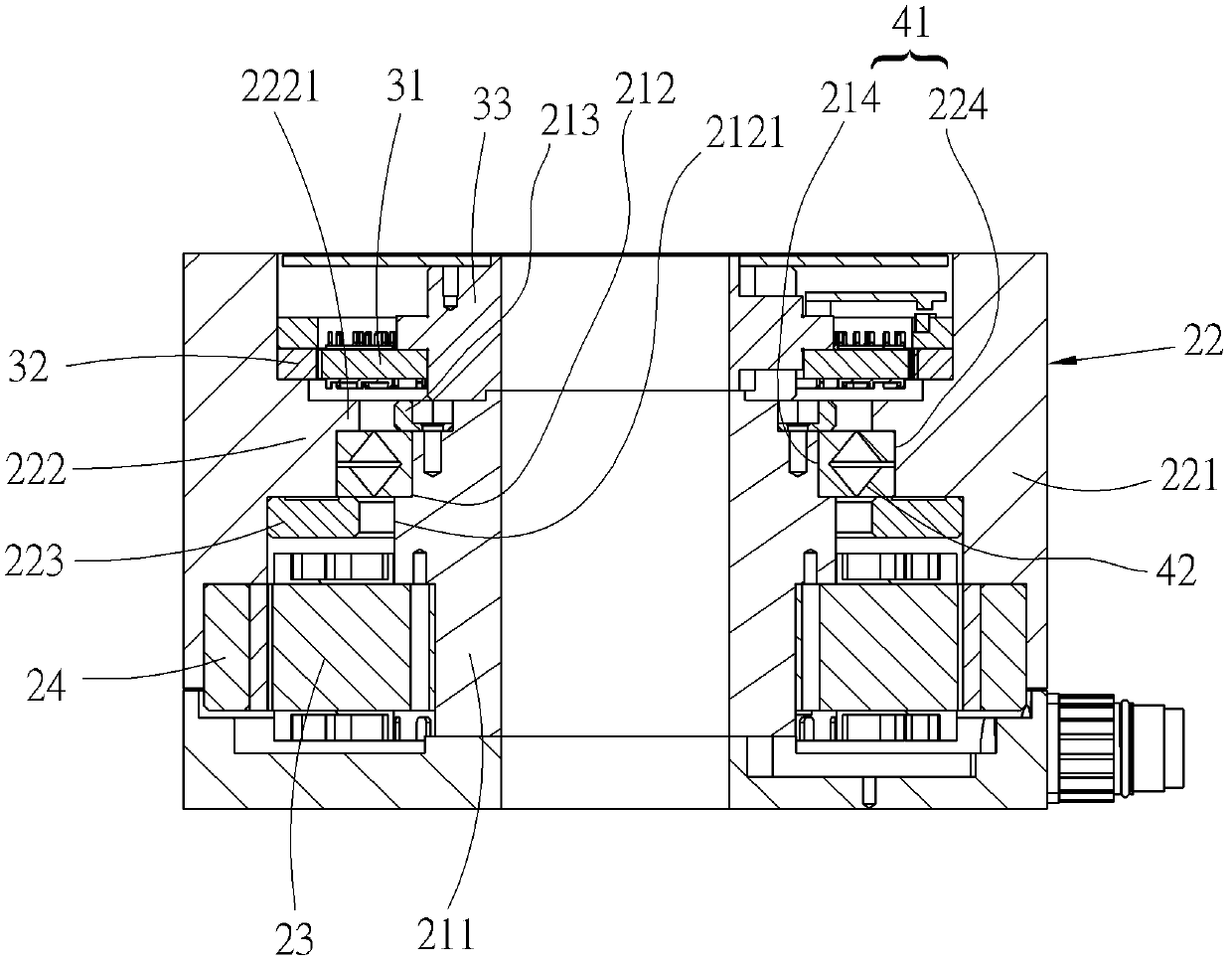
[0029] Below, see Figure 1 to Figure 3 As shown, the motor structure 10 with a resolver provided in a preferred embodiment of the present invention mainly includes a motor unit 20 , a resolver unit 30 and a bearing portion 40 .

[0030] The motor unit 20 is an external rotation type, and has a hollow mandrel 21, an annular casing 22 whose inner diameter is larger than the outer diameter of the mandrel 21, coaxially threaded on the mandrel 21, and makes the inner side of the shell 22 The radial annulus of the mandrel 21 and the radial annulus on the outside of the mandrel 21 face each other and are separated from each other, a stator part 23 is fixed around the bottom end of the mandrel 21 outside the annulus, and a rotor part 24 is fixed around the bottom end of the inner ring surface of the casing 22, and moves relative to the stator part 23 under the action of magnetic force. of the same.

[0031] The resolver unit 30 also belongs to the conventional sensing technology us...


PUM


Abstract

The invention provides a motor structure provided with a resolver. The motor structure comprises a motor unit, a resolver unit and a bearing part. The motor unit is provided with a mandrel, an annular shell, a stator part and a rotor part, wherein the annular shell is coaxially sheathed on the mandrel, an outer annular face in the radial direction of the mandrel and an inner annular face in the radial direction of the shell are enabled to face each other and be separated from each other, and the stator part and the rotor part are coaxially and correspondingly arranged between the opposite annular faces of the mandrel and the shell respectively. The resolver unit is located on one axial end of the mandrel. The bearing part is provided with an annular bearing socket which is located between the opposite annular faces of the mandrel and the shell and is located between the resolver unit and the stator part and the rotor part of the motor unit, wherein a bearing is accommodated in the bearing socket. According to the invention, the bearing is arranged between the motor unit and the resolver unit to extend the distance between the motor unit and the resolver unit and reduce possible interference. Meanwhile, an appropriate barrier is formed between the motor unit and the resolver unit through the arrangement of the bearing so as to achieve a specific effect of effective interference reduction in a multiplied way.

Description

technical field [0001] The present invention relates to motors, and more particularly to a motor configuration with a resolver. Background technique [0002] At present, the resolver is used to analyze the angular position of the motor rotation and provide the corresponding position information for motor control. Therefore, in terms of spatial structure, the resolver is usually attached to one end of the motor shaft to make the resolver The rotor in the angler rotates synchronously with the motor, and outputs a corresponding amplitude modulation signal through the change of the magnetic field. After analysis, the corresponding motor rotation position information can be obtained. However, both the motor and the resolver use electric energy as their power source, and use the change of the magnetic field to convert the electric energy into mechanical energy to generate power, or sense the change of the magnetic field to generate a corresponding amplitude modulation signal, and ...

Claims


Application Information

Patent Timeline
Patent Type & Authority Applications(China)
IPC IPC(8): H02K11/00H02K5/16H02K5/04H02K11/21
Inventor 王之佑
Owner HIWIN MIKROSYST
Why Eureka
Try Eureka