
Planing device

A planing and equipment technology, applied in the field of planing equipment, can solve the problems of expensive planing equipment, failure, stress concentration, etc., and achieve the effect of preventing material gap effect and improving durability

Inactive Publication Date: 2013-09-18
THIELE GMBH & CO KG
View PDF5 Cites 0 Cited by
  • Summary
  • Abstract
  • Description
  • Claims
  • Application Information

AI Technical Summary

Problems solved by technology

Cracks lead to stress concentrations and premature failures and thus costly shutdowns of the entire planing plant

Method used


Image

  • Planing device
  • Planing device
  • Planing device

Examples


Embodiment Construction

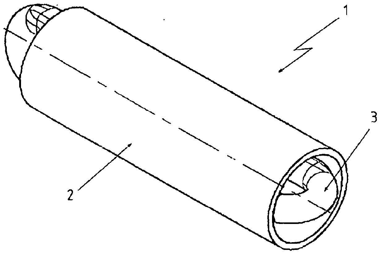
[0039] figure 1 Shown is a part of a planing device 1 according to the invention. The planing device 1 includes a channel 2 of a planer chain guide (Hobelkettenfuehrung), not shown in further detail, in which channel a planer chain 3 is guided and supported.

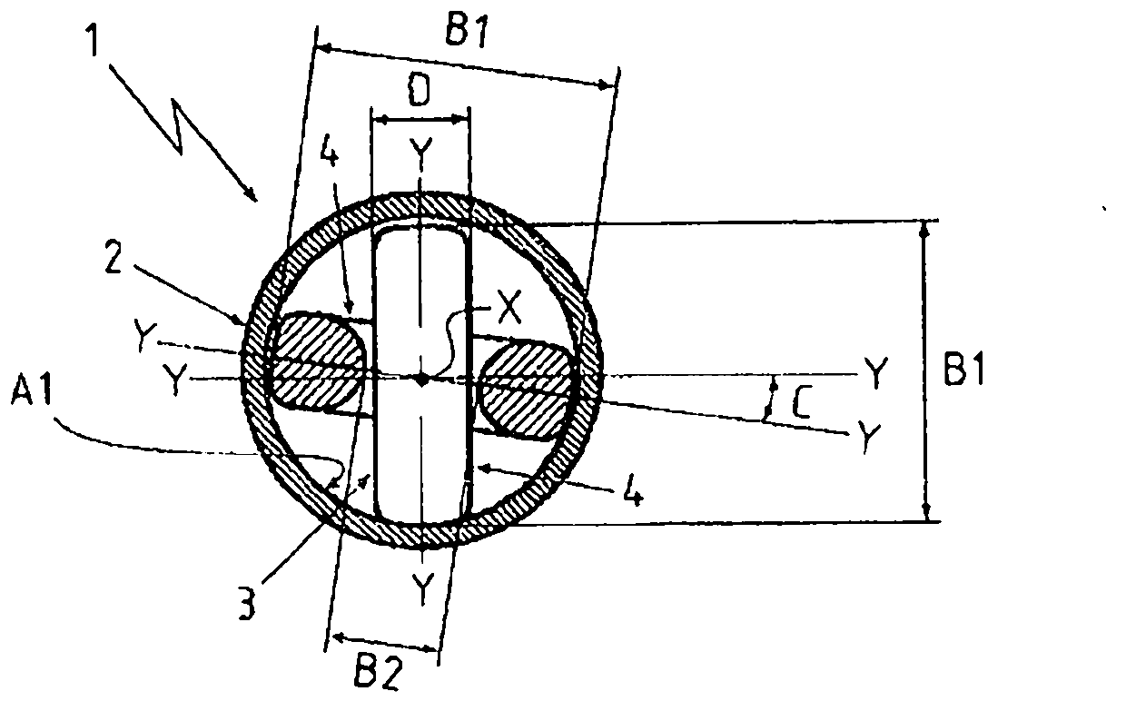
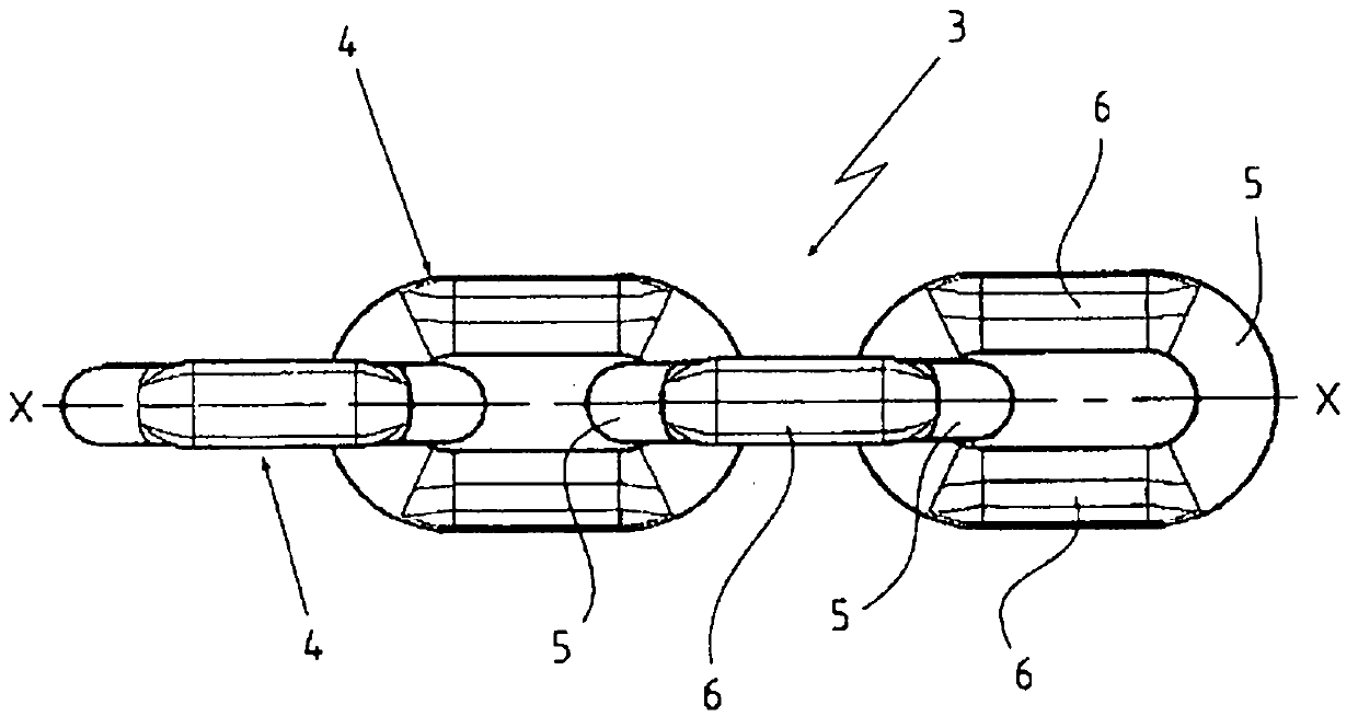
[0040] figure 2 by figure 1 The shown sectional view of the planing device 1 illustrates the guidance of the planing chain 3 within the channel 2 . Channel 2 has a circular cross section. The plow chain 3 is guided within the channel 2 with play to its inner wall with the inner radius A1. The gap is within a range which results from the ratio of the outer width B1 of the link 4 to the inner radius A1 of the channel 2 of between 1:0.5 and 1:0.6. It can be seen in the figure that the planer chain 3 is composed of chain links 4 arranged one by one in the channel 2 and hung together. Each link 4 has the same outer width B1 and thickness D in the direction of its respective transverse axis Y and thus in the transverse ...


PUM


Abstract

The invention relates to a planing device having a planing chain which is guided inside a channel (2) having an inside radius (A1) and the chain links of which each have chain plates (5) and chain pins (6) connecting the latter. In cross section, the chain pins (6) each have an outside radius that extends along a chord length, wherein the inside radius (A1) of the channel (2) and the outside radius of the chain pins (6) are at a ratio of from 1:0.8 to 1:1.2 to one another.

Description

technical field [0001] The invention relates to a planing device comprising a planing chain as characterized in the preamble of claim 1 . Background technique [0002] Coal plows are used in underground operations for stripping coal. The drive is carried out by a tensioning element in the form of a plow chain which reciprocates the plow in the coal face between two sections parallel to the coal face of the seam. The obtained ore and coal are transported out by chain scraper conveyor. The chain scraper conveyor is at the same time the guiding device, running track and support for the coal plow. The plow chain itself is guided and supported in corresponding channels of the plow chain guide. [0003] Planer chains are subject to strong loads in use. In addition to high tensile loads and impact loads, high frictional forces are added. This friction occurs mainly in the channel and in the deflection area. The resulting high wear of the individual chain links and of the chai...

Claims


Application Information

Patent Timeline
Patent Type & Authority Applications(China)
IPC IPC(8): E21C29/14F16G13/12
CPCE21C29/14F16G13/12E21C27/34
Inventor B·H·舍夫G·菲利普D·福韦尔克
Owner THIELE GMBH & CO KG
Learn More