
Steel coil emptying machine

A technology of feeding machine and steel coil, applied in the field of steel structure engineering, can solve the problem of lack of steel coil feeding machine, etc., and achieve the effect of preventing inconsistent speed and uniform feeding

Inactive Publication Date: 2013-09-25
朱卫国
View PDF8 Cites 3 Cited by
  • Summary
  • Abstract
  • Description
  • Claims
  • Application Information

AI Technical Summary

Problems solved by technology

[0003] The technical problem to be solved by the present invention is to provide a long service life, safe, reliable, economical and applicable steel coil unwinding machine for the defect of lack of steel coil unwinding machine in the production of existing assembly line equipment for veneer steel-wood formwork

Method used


Image

  • Steel coil emptying machine
  • Steel coil emptying machine
  • Steel coil emptying machine

Examples


Embodiment Construction

[0015] The technical solutions of the present invention will be further described below in conjunction with the embodiments and the accompanying drawings.

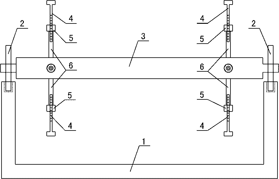
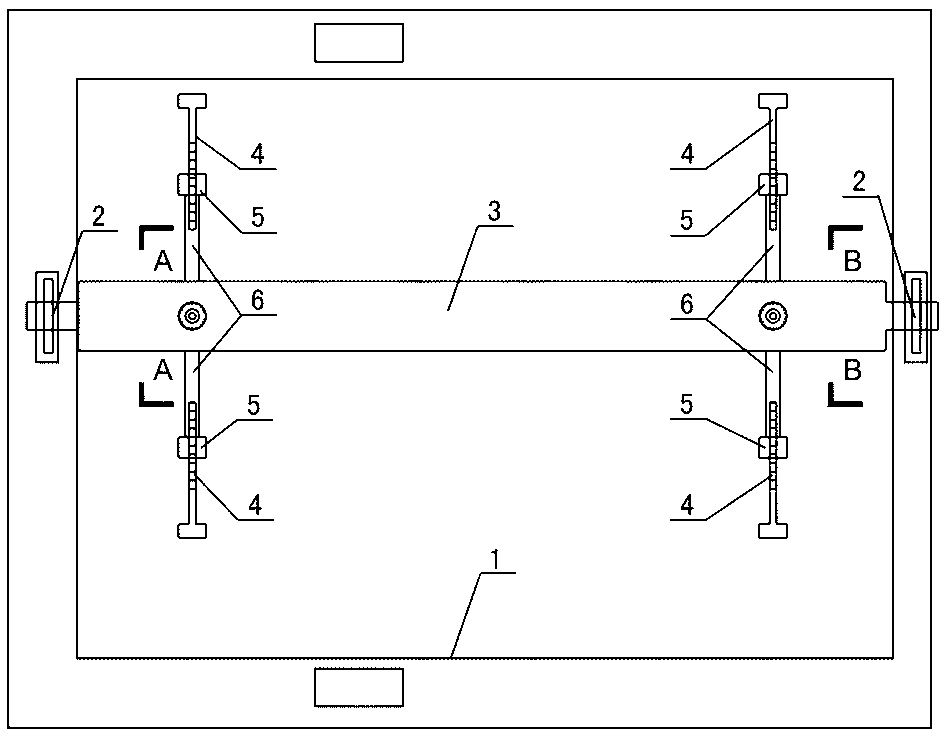
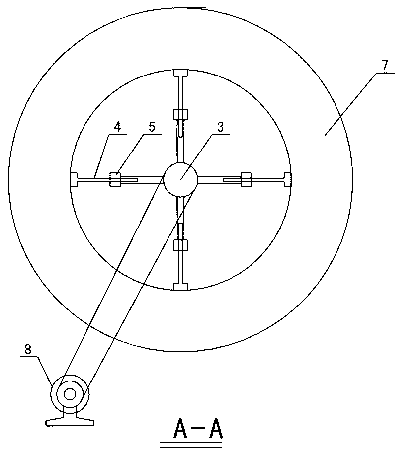
[0016] refer to Figure 1~Figure 4 As shown, the steel coil unwinding machine of the present invention includes a fixed support 1, a bearing seat 2 and a bearing 3, the front of the fixed support 1 is U-shaped, and the side is T-shaped, and the fixed support 1 Both sides are provided with semicircular arc surfaces, and the two ends of the bearing seat 2 are respectively arranged on the semicircle arc surfaces on both sides of the fixed bracket 1, the bearing 3 is installed in the bearing seat 2, and the bearing 3 There are at least two bolt groups on the radial periphery, and each bolt group includes at least three fixing nuts 5 and the same number of adjusting screw rods 4 as the fixing nuts 5, and the fixing nuts 5 in each bolt group are welded on the round tube 6 Above, the round pipe 6 is fixed on the radial periphery...


PUM


Abstract

The invention provides a steel coil emptying machine. The steel coil emptying machine comprises a fixing support, a bearing seat and a bearing, wherein the front surface of the fixing support is of a U shape, and the side surface of the fixing support is of a T shape; semicircular arc surfaces are formed on both sides of the fixing support; two ends of the bearing seat are respectively arranged on the semicircular arc surfaces at two sides of the fixing support; the bearing is installed in the bearing seat; the radial outer periphery of the bearing is provided with at least one bolt group; each bolt group at least comprises three fixed nuts as well as regulating screw rods with the same number of the fixed nuts; the fixed nuts in each bolt group are all welded on a round tube; the round tube is fixed on the radial outer periphery of the same cross section of the bearing; each regulating screw rod is correspondingly connected with a fixed nut threadedly. The steel coil emptying machine provided by the invention has the beneficial effects that an assembly line production device of a veneering steel wood mold plate is matched to operate, so that the uniform emptying of steel coils is ensured; the emptying speed is controlled; inconsistent emptying speed or steel coil springing back in emptying is prevented.

Description

technical field [0001] The invention belongs to the technical field of the construction industry, in particular to the field of auxiliary equipment for the production of veneered steel-wood formwork lines and steel structure engineering, and in particular to a steel coil unwinding machine. Background technique [0002] In the construction of reinforced concrete on the floor of a house, the consumption of wooden formwork used as floor support is very large. Affected by the working environment, the number of turnovers of wooden formwork is 4 to 6 times, its service life is low, and wood waste is serious; this is bound to increase The construction cost of floor engineering projects also causes waste of limited timber resources and environmental pollution to the country. For this reason, application number 201210511770.3 discloses an assembly line production equipment for veneer steel-wood formwork, which consists of punching and forming equipment and veneer wrapping equipment. ...

Claims


Application Information

Patent Timeline
Patent Type & Authority Applications(China)
IPC IPC(8): B21C47/18
Inventor 朱卫国李敦平王朝晖
Owner 朱卫国
Features
  • Generate Ideas
  • Intellectual Property
  • Life Sciences
  • Materials
  • Tech Scout
  • Unparalleled Data Quality
  • Higher Quality Content
  • 60% Fewer Hallucinations
Learn More