
Liftable long shaft placement device

A lifting shaft, long shaft technology, applied in the direction of tool storage devices, manufacturing tools, etc., can solve the problem of wear and tear of the shaft end of the shaft, and achieve the effect of preventing wear or deformation and avoiding wear and tear.

Inactive Publication Date: 2013-09-25
SUZHOU SUTENG ELECTRONICS TECH
View PDF8 Cites 0 Cited by
  • Summary
  • Abstract
  • Description
  • Claims
  • Application Information

AI Technical Summary

Problems solved by technology

[0003] (1) During normal storage, the end of the shaft or the shaft body is worn due to rolling or sliding;

Method used

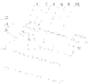
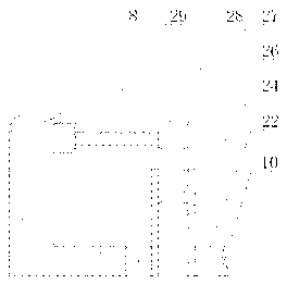

Image

  • Liftable long shaft placement device
  • Liftable long shaft placement device

Examples


Embodiment Construction

[0018] The present invention will be further described in detail below in conjunction with the drawings

[0019] Such as figure 1 with figure 2 As shown, the present invention includes a bottom plate 10 and an accommodating space 6 arranged on the bottom plate 10. The accommodating space 6 also includes at least two supports 1 arranged on the same line, and the support 1 includes a concave support arranged on the top. Part 2 and a lifting part arranged below the supported part 2 for driving the support part 2 to move up and down.

[0020] In the first embodiment of the present invention, the lifting part includes a lifting shaft 26 arranged at the bottom of the supporting part 2, and a hollow sleeve 24 connected to the bottom plate 10 through a bearing 22, and at least part of the lifting shaft 26 is provided with external threads , The sleeve 24 is provided with internal threads, and the lifting shaft 26 is connected to the sleeve 24 by threads.

[0021] In this embodiment, the l...


PUM


Abstract

The invention discloses a liftable long shaft placement device which comprises a bottom plate and a containing space arranged on the bottom plate. The liftable long shaft placement device is characterized in that at least two supports arranged on the same straight line are placed in the containing space, and each support comprises a concave supporting portion and a lifting portion, wherein the supporting portion is arranged at the top, and the lifting portion is arranged below the supporting portion and used for driving the supporting portion to move up and down. Two ends of a long shaft are placed in the concave supporting portions of the supports, contact surfaces of the supporting portions and the ends of the long shaft are curved surfaces and are large in area, so that sliding and rolling of the long shaft can be greatly limited, and abrasion or deformation of the long shaft due to sliding and rolling is prevented. After the long shaft is placed, the long shaft drops to the bottom of a box by the aid of the lifting portions arranged below the supporting portions, and the long shaft is raised and accordingly taken out by the aid of the lifting portions when needing to be used, so that abrasion of the long shaft due to complete exposure in the preservation process is avoided.

Description

Technical field [0001] The invention relates to the field of machining, in particular to a jig used for arranging long shaft parts. Background technique [0002] Long shaft workpieces are shaft parts with a relatively large ratio of length to diameter. Such parts will encounter at least the following situations in the usual process of inclusion: [0003] (1) During normal storage, the end of the shaft or the shaft body is worn due to rolling or sliding; [0004] (2) During normal storage, the shaft body is deformed under the action of radial force; [0005] In view of this, the present invention has studied the above-mentioned shortcomings in the prior art, and this case was born. Summary of the invention [0006] The technical problem to be solved by the present invention is to provide a method capable of reducing the wear of long shaft workpieces during placement. [0007] The present invention provides a vertical axis placing device that can be raised and lowered, which includes a b...

Claims


Application Information

Patent Timeline
Patent Type & Authority Applications(China)
IPC IPC(8): B25H3/02
Inventor 周天毫
Owner SUZHOU SUTENG ELECTRONICS TECH
Learn More