

Traction pin for locomotive traction device
A traction device and traction pin technology, which is applied to traction devices, transportation and packaging, railway car body parts, etc., can solve the problems of large wear, difficult disassembly, and shorten the service life of the connecting pin 12, so as to improve the service life and avoid failure. Dismantling, uniform wear effect
- Summary
- Abstract
- Description
- Claims
- Application Information
AI Technical Summary
Problems solved by technology
Method used
Image

Examples
Embodiment Construction
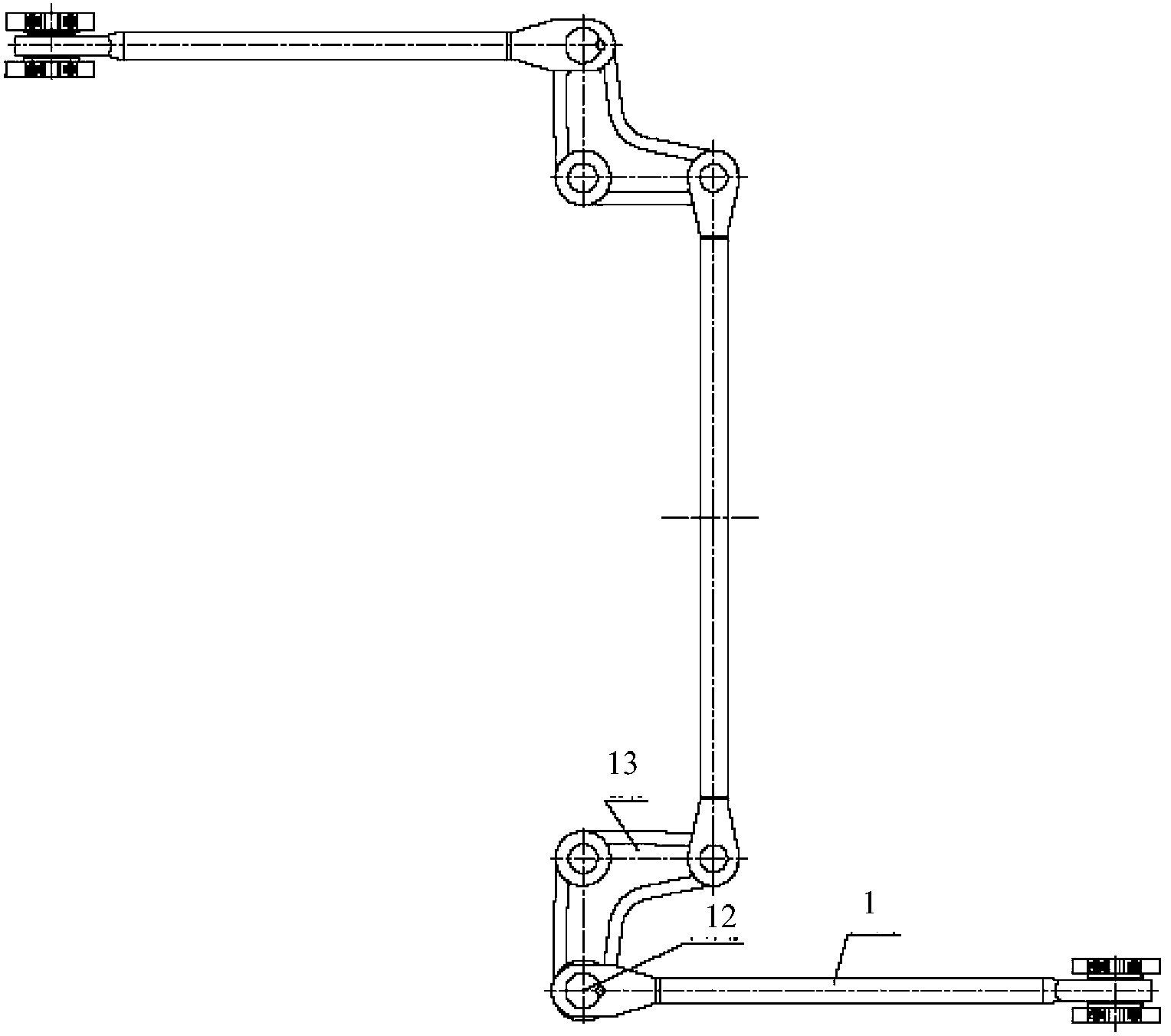
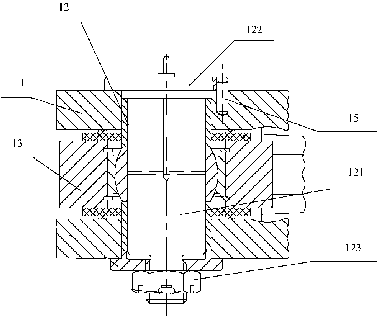
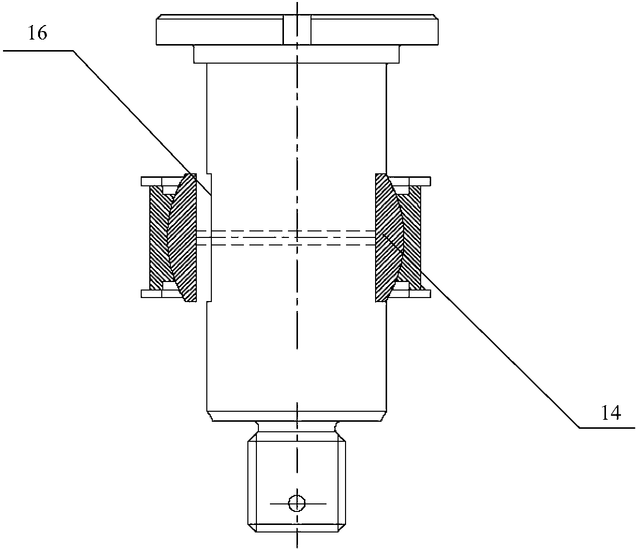
[0015] Figure 4 It is a structural schematic diagram of an embodiment of a traction pin for a locomotive traction device of the present invention; Figure 5 for Figure 4 Schematic diagram of the connection structure of the traction pin for the locomotive traction device, the drawbar and the crank arm in ; please refer to Figure 4 and Figure 5 , the present embodiment provides a traction pin for a locomotive traction device, including a cylindrical pin body 20, the top of the pin body 20 is fixedly provided with a first positioning plate 21 with a cross-sectional area larger than the pin body 20, the pin body The bottom end of 20 is provided with a second positioning plate 22 for cooperating with the first positioning plate to axially fix the pin shaft body 20, and the second positioning plate 22 can rotate coaxially relative to the pin shaft body 20; The bottom end includes a first shaft section 201 and a second shaft section 202 in sequence. The diameter of the first s...
PUM
 Abstract
Description
Claims
Application Information