Knife tool arc edging device

An arc edge and tool technology, which is used in manufacturing tools, parts of grinding machine tools, grinding/polishing equipment, etc. problems, to achieve the effect of uniform grinding wheel wear, convenient size and position adjustment, and improve the quality of sharpening

Inactive Publication Date: 2007-10-24
林志贺
View PDF0 Cites 20 Cited by
  • Summary
  • Abstract
  • Description
  • Claims
  • Application Information

AI Technical Summary

Problems solved by technology

At present, the rigidity of the main shaft of the traditional tool sharpening machine on the market is poor, the sharpening quality is not ideal, and the operation flexibility is also poor; in addition, when adjusting the sharpening angle, the height of the knife tip from the grinding wheel surface and the front and back will have a large difference. Changes, so that after adjusting the inclination angle, it is necessary to adjust the height of the tool tip and the front and rear feed position, especially when the inclination angle adjustment changes greatly, such as double relief angle; in addition, it is difficult to perform circular negative chamfering and blunt round edge grind

Method used


Image

  • Knife tool arc edging device
  • Knife tool arc edging device
  • Knife tool arc edging device

Examples


Embodiment 1

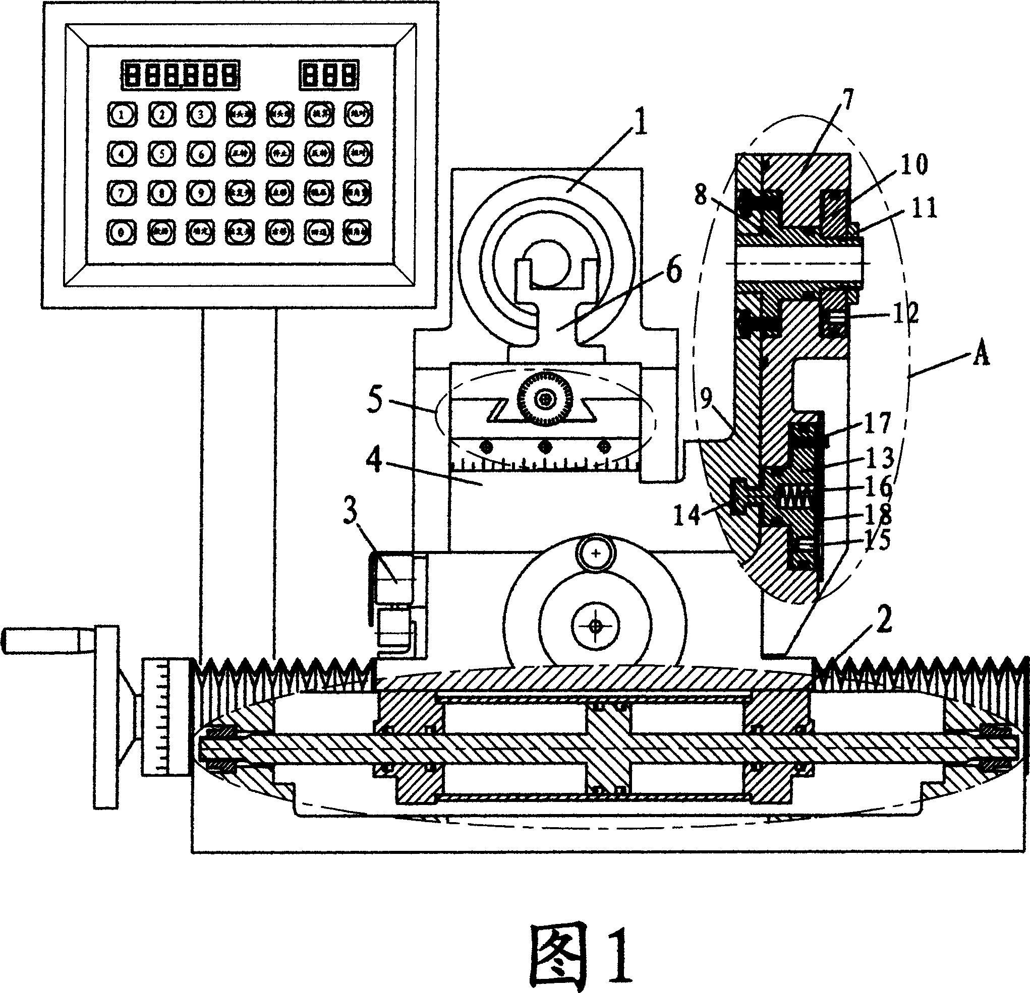
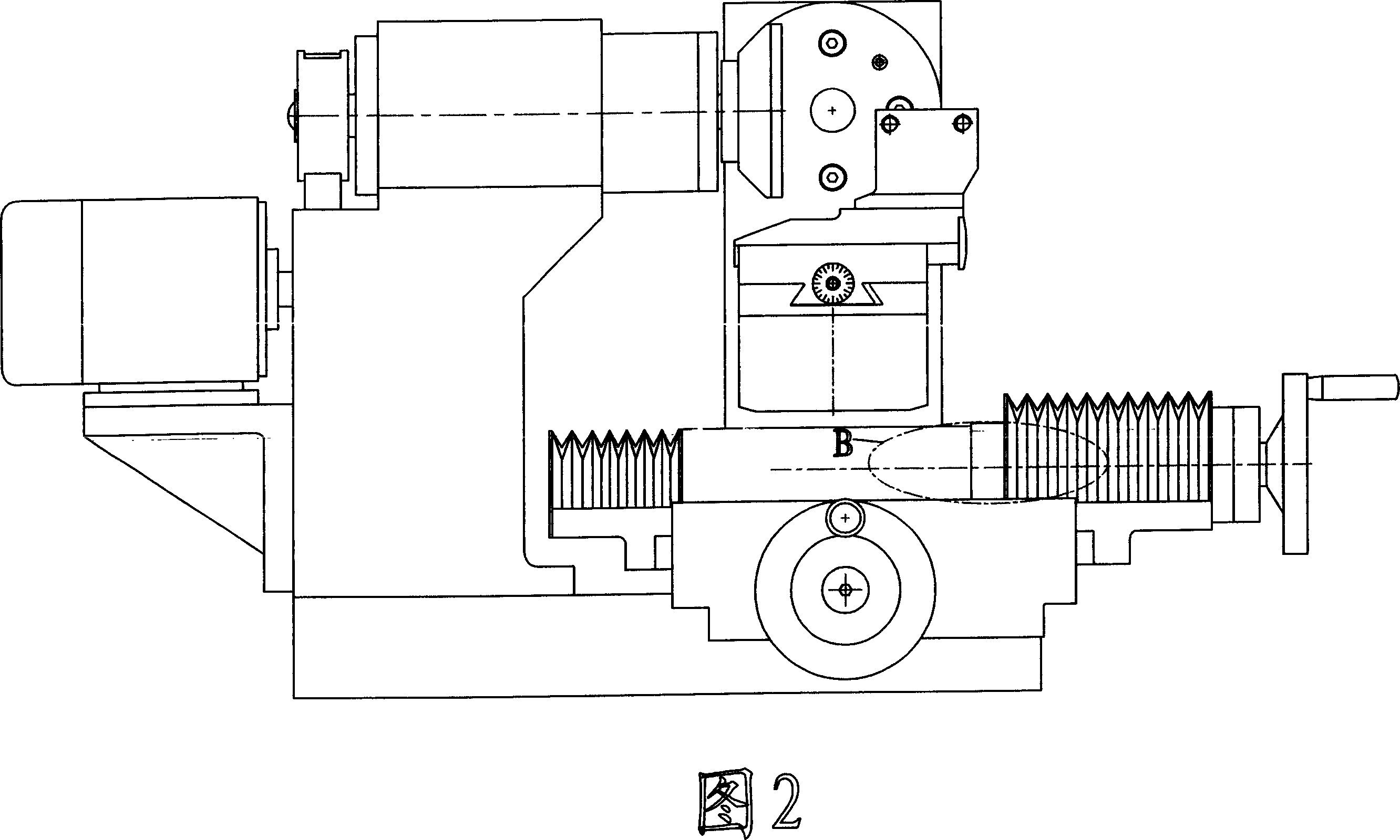
[0022] Shown with reference to Fig. 1, 2, present embodiment grinding head assembly (1) conjoined is installed on the body, and it can effectively improve the rigidity of grinding head. The cross slide adopts a rolling guide rail structure, which has a small friction coefficient, stable movement, and high precision, which is especially beneficial to steady-pressure feed and low-speed reciprocating movement. A biaxial cylinder (2) and a set of clutch screw mechanism are installed in the longitudinal axis slide seat of the cross slide seat; When cutting the blade, separate the screw nut, and then use the double-axis cylinder (2) to perform automatic reciprocating motion; when sharpening milling cutters and other tools, connect the ventilation pipes at both ends of the double-axis cylinder (2) to the outside air, and then close the The screw nut is used to drive the screw when the screw is directly rotated, so that it is easy to operate. A screw adjustment mechanism (B) and a gr...

Embodiment 2

[0026] With reference to shown in Fig. 5, present embodiment and the first embodiment structurally have increased lifting mechanism between the inclination block of inclination mechanism and the rotary table; Worm drive mechanism; In addition, the double-axis cylinder and the clutch screw mechanism installed on the vertical axis slide seat are replaced with the transmission mechanism of the stepper motor driving the rolling screw.

[0027] With reference to Fig. 5, shown in 6, the elevating mechanism of the present embodiment mainly consists of the inclination block (9) of the inclination mechanism, the base (25) of the rotary table, the gap adjustment block (26), the special nut bar (27), the special Bolt (28), bevel gear shaft (29), intermediate pin (30) form. The base of the rotary table (25) is processed with a dovetail protrusion in the direction of its axis of rotation, and the inclination block (9) of the inclination mechanism is processed with a dovetail groove matchin...


PUM


Abstract

The invention relates to a tool arc girnIt mainly comprises the body, the grinding head assembly, cross sledge, oblique angle, return working platform. It features in the grinding head and cross sledge connected to or installed on the body, oblique angle installed between the cross sledge and the return working platform which installs the sub crossing sledge with cutter carrier on it. The axial core of the oblique structure ranges within the 10 mm of the extended radius of the return shaft core and one half of the outer radius of the end surface of the sand wheel. It has strong rigidity, fine grinding quality, convenient adjustment, applicable for fine grinding.

Description

technical field [0001] The invention relates to a cutter arc device, in particular to a cutter arc sharpening device for machining a cutter. technical background [0002] With the popularization and application of cutting tools made of superhard materials such as diamond, cubic boron nitride, and ceramics, especially the new trend of turning grinding instead of grinding, people have become more and more demanding on the sharpening of turning tools. Traditional manual grinding of turning tools It has been difficult to meet the requirements, especially in terms of finish, which has prompted people to pay more and more attention to machine grinding tools. At present, the rigidity of the main shaft of the traditional tool sharpening machine on the market is poor, the sharpening quality is not ideal, and the operation flexibility is also poor; in addition, when adjusting the sharpening angle, the height of the knife tip from the grinding wheel surface and the front and back will ...

Claims


Application Information

Patent Timeline
Patent Type & Authority Applications(China)
IPC IPC(8): B24B3/58B24B41/04
Inventor 林志贺
Owner 林志贺
Why Eureka
Try Eureka