
Touch panel and touch display device provided with same

A touch panel, touch display technology, applied in the input/output process of data processing, instruments, electrical digital data processing, etc. Enhance the anti-ESD ability and reduce the effect of misjudgment

Inactive Publication Date: 2013-09-25
INTERFACE OPTOELECTRONICS SHENZHEN +1
View PDF3 Cites 2 Cited by
  • Summary
  • Abstract
  • Description
  • Claims
  • Application Information

AI Technical Summary

Problems solved by technology

However, due to space limitations, many metal traces may not go out of a straight line during the design of the traces, making it difficult for the production line personnel to make a quick judgment, which may lead to misjudgments in actual operation and affect the quality of the product
In addition, due to the large number of conductive signal lines in the routing area, it is easy to generate electrostatic interference

Method used


Image

  • Touch panel and touch display device provided with same
  • Touch panel and touch display device provided with same
  • Touch panel and touch display device provided with same

Examples


Embodiment Construction

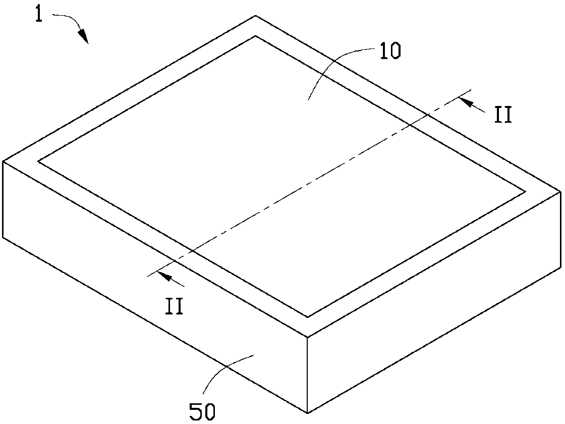
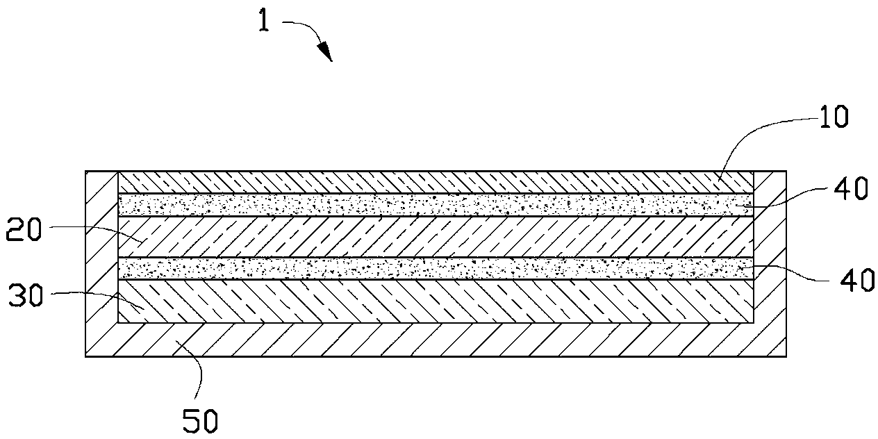
[0015] see figure 1 and figure 2 , the touch display device 1 provided by the present invention includes a glass cover 10 , a touch panel 20 , a display module 30 and a casing 50 . The touch panel 20 and the display module 30 are accommodated in the accommodation space formed by the glass cover 10 and the casing 50 .

[0016] The glass cover 10 , the touch panel 20 and the display module 30 are stacked with each other. The touch panel 20 is glued together with the glass cover 10 and the display module 30 through optical glue 40 . The optical glue 40 may be, but not limited to, an adhesive with high light transmittance such as optical clear adhesive (Optical Clear Adhesive, OCA) or optical clear resin (Optical Clear Resin, OCR).

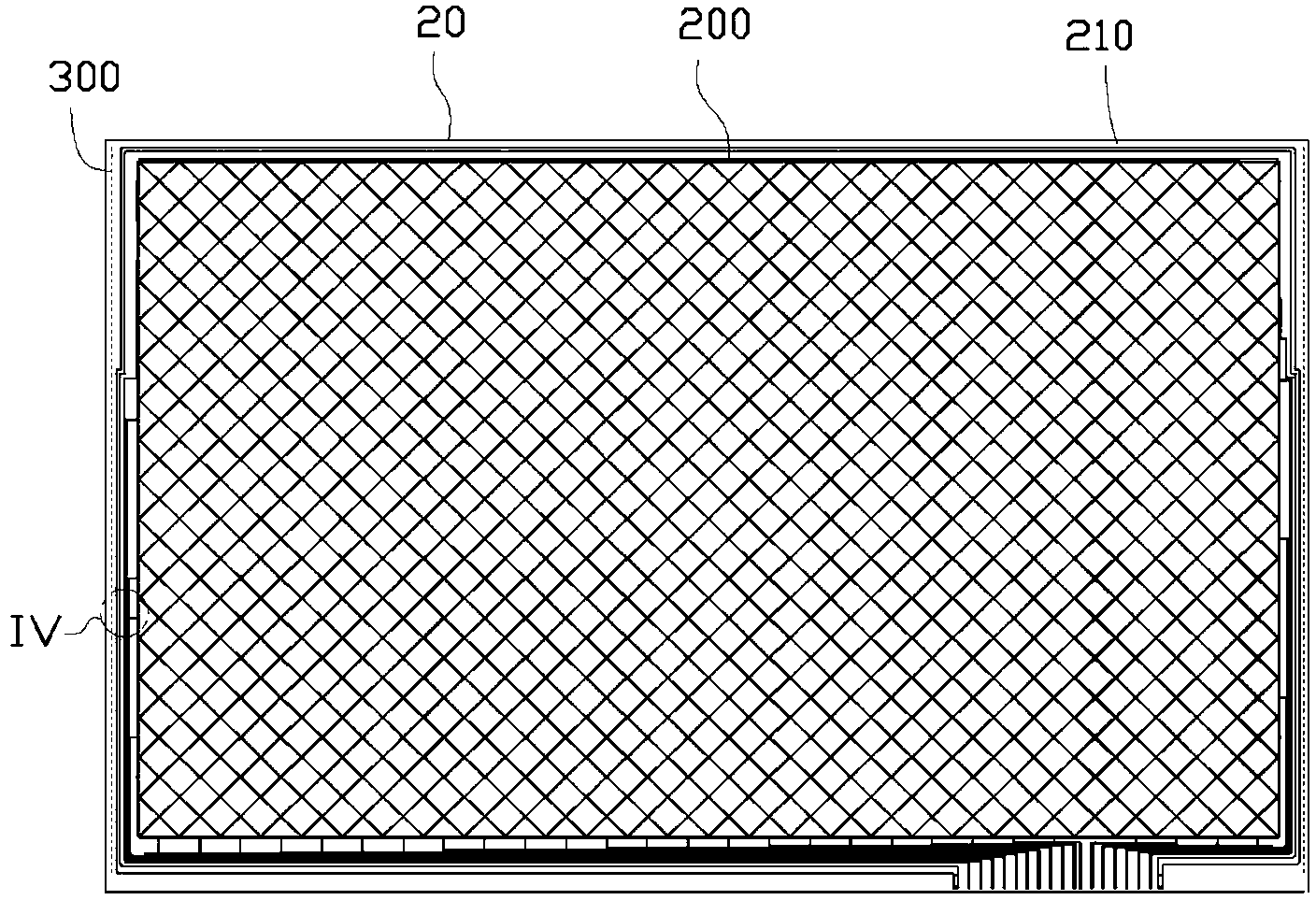
[0017] see image 3 As shown, the touch panel 20 includes a touch area 200 and a wiring area 210 located around the touch area 200 and surrounding the touch area 200 . The wiring area 210 is used for wiring design of the conductive signal lines ...


PUM


Abstract

Provided are a touch panel and a touch display device provided with the same. The touch panel comprises a touch region and a wiring region located on the periphery of the touch region and surrounding the touch region. The wiring region comprises various conductive signal wires required by the touch panel, at least one starved inspection reference line is arranged in the wiring region, formed by arranging multiple metal blocks at intervals, located on the outer sides of the conductive signal wires in the wiring regions and used in the bonding manufacture process of the display device using the touch panel, and inspectors can conveniently perform starvation inspection by means of a method for inspecting whether optical cement covers the starved inspection reference line or not. The touch panel is provided with one starved inspection reference line in the wiring region, so that the inspectors can conveniently and quickly perform starvation inspection in the bonding manufacture process of the touch panel and a glass cover plate of the touch display device.

Description

technical field [0001] The invention relates to a touch panel and a touch display device with the touch panel. Background technique [0002] A touch panel applied to various touch display terminals includes a touch sensing area and a wiring area located around the touch sensing area. At present, optical adhesives are mostly used to bond the touch panel and the glass plate that protects the touch panel, such as OCR (Optical Clear Resin, optically transparent resin) and OCA (Optical Clear Adhesive, optically transparent adhesive). In the process of using optical glue to bond the touch panel to the glass plate, when the production line personnel detect the lack of glue, the basis for judging the lack of glue is to see with the naked eye whether the optical glue has completely covered all the metal traces in the wiring area. Line (metal trace). However, due to space limitations, many metal traces may not go out of a straight line during the design of the traces, making it diff...

Claims


Application Information

Patent Timeline
Patent Type & Authority Applications(China)
IPC IPC(8): G06F3/041
Inventor 曹昌李嘉益
Owner INTERFACE OPTOELECTRONICS SHENZHEN
Learn More