Constrained knee prosthesis

A knee joint prosthesis and prosthesis technology, applied in the field of knee joint prosthesis, can solve problems such as biomechanical inefficiency

Active Publication Date: 2013-09-25
SMITH & NEPHEW INC
View PDF12 Cites 4 Cited by
  • Summary
  • Abstract
  • Description
  • Claims
  • Application Information

AI Technical Summary

Problems solved by technology

While constrained knee replacement systems can provide the desi

Method used


Image

  • Constrained knee prosthesis
  • Constrained knee prosthesis
  • Constrained knee prosthesis

Examples


Embodiment Construction

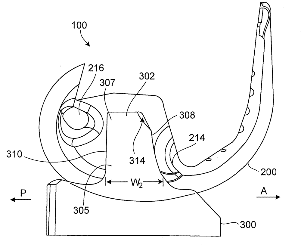
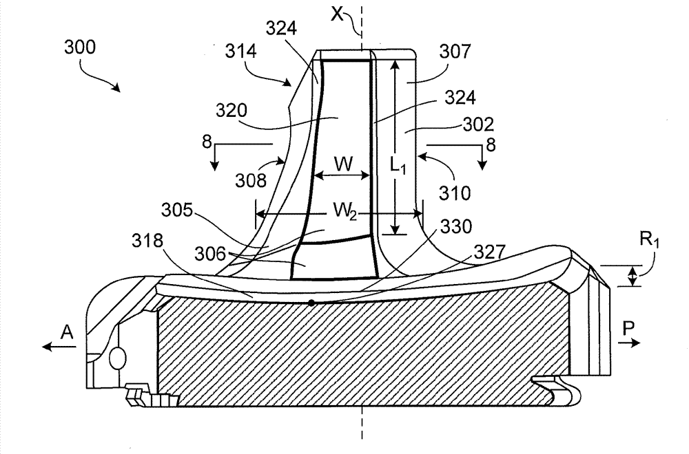
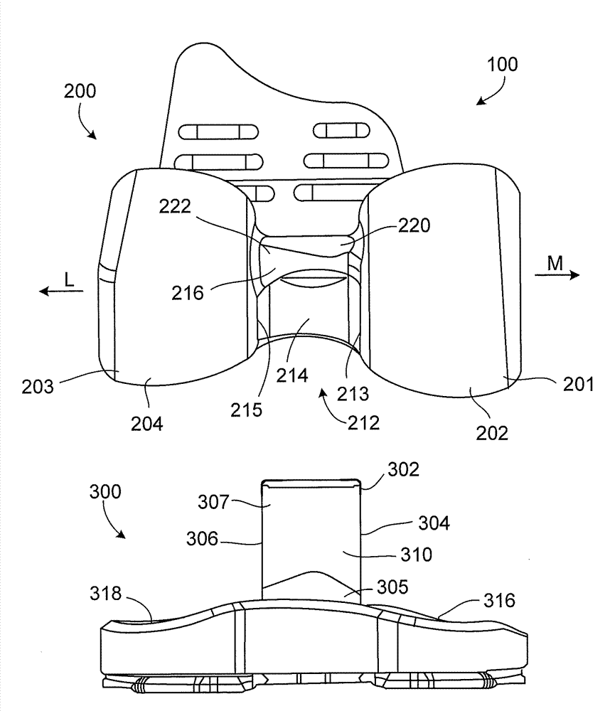
[0023] refer to figure 1 and 2 , the knee prosthesis 100 provides varus / valgus constraint and also allows internal and external rotation of the tibia relative to the femur. To this end, knee prosthesis 100 includes tibial insert 300 that is shaped to engage femoral component 200 to (i) limit tibial varus-valgus deviation from its proper alignment with the femur, and (ii) promote tibial Rotation relative to the femur during flexion. Tibial insert 300 may be referred to as a constrained insert that is constrained by femoral component 200 in assembled knee prosthesis 100 .

[0024] During flexion in a healthy knee, the tibia rotates a small amount about its longitudinal axis (internal-external rotation). Knee prosthesis 100 enables this rotation to help maintain a natural feel for the reconfigured knee. Internal rotation of the tibia relative to the femur (tibiofemoral rotation) aligns the line of action of the quadriceps with the tibia, improving quadriceps efficiency compar...


PUM


Abstract

A tibial insert includes a base and a post extending from the base along a longitudinal axis. The post has a medial surface, a lateral surface, and a height along the longitudinal axis. The medial surface has a medial section, and the lateral surface has a lateral section oriented substantially parallel to the medial section. The medial section and the lateral section each have a width in a substantially anterior-posterior direction that is sufficient to enable varus/valgus constraint over a flexion/extension range from extension to about 90 to 120 degrees of flexion when the tibial insert is mated with a femoral component.

Description

[0001] Cross References to Related Applications [0002] This application claims priority and the full benefit of US Provisional Application Serial No. 61 / 436,788, filed January 27, 2011, and entitled "Constrained Knee Prosthesis," the entire contents of which are incorporated herein by reference. technical field [0003] The present disclosure relates to knee prostheses. Background technique [0004] Total knee replacement systems often include tibial and femoral implants that replace the articular surfaces of the knee. Posterior stabilized knee replacement systems can be used to replace the function of both the anterior cruciate ligament (ACL) and posterior cruciate ligament (PCL). In some cases, posterior stabilized knee replacement systems include varus / valgus constraints to also replace the function of the medial collateral ligament (MCL) and lateral collateral ligament (LCL). While constrained knee replacement systems can provide the desired stability, they often int...

Claims


Application Information

Patent Timeline
IPC IPC(8): A61F2/38A61F2/30
CPCA61F2/384A61F2/3859A61F2/3868A61F2/3886A61F2/389A61F2/4684
Inventor B·W·麦金农N·M·伦茨S·K·拉斯特M·D·里斯S·B·哈斯
Owner SMITH & NEPHEW INC
Why Eureka
Try Eureka