
Clamping device of injection molding machine mould

A technology for injection molding machines and molds, which is applied in the field of clamping devices for injection molding machine molds, and can solve the problems of pads 23 not being installed in place, unreliable clamping, and low clamping efficiency, so as to achieve fast and convenient clamping and avoid padding Insufficient installation, good versatility

Inactive Publication Date: 2013-10-02
WUXI MATEX PRECISION
View PDF4 Cites 2 Cited by
  • Summary
  • Abstract
  • Description
  • Claims
  • Application Information

AI Technical Summary

Problems solved by technology

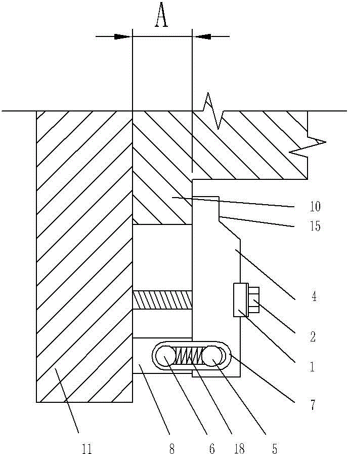
[0002] The two sides of the mold of the injection molding machine are fixed on two opposite installation surfaces 11 in the axial direction of the injection molding machine. When clamping, the clamp block 24 is pressed tightly on the flange part 10 of the mold clamping end surface by the bolt 22 to press the mold on the mold. On the mounting surface 11, a spacer 23 with the same thickness d' and the thickness d of the flange part 10 is placed between the clamp block 24 and the mounting surface 11 to ensure that the mold is evenly stressed so as to realize reliable clamping of the mold. See Image 6 , its disadvantage is that: because the spacer 23 and the clamping block 24 are split structures, the clamping is inconvenient and the clamping efficiency is low. 22 tightening, since most of the injection molds are vertically installed and fixed, and the volume and quality of the fixed block 23 are relatively large, it is easy to injure people due to the fall of the cushion block 23 during clamping, and there is a greater potential safety hazard; At the same time, it is easy to appear that the cushion block 23 is not in place during the installation process, thereby causing the problem of unreliable clamping; in addition, the thickness d of the flange part 10 of different molds is different, and the cushion block 23 of the corresponding thickness is required. , thus increasing tooling reserves and high production costs

Method used


Image

  • Clamping device of injection molding machine mould
  • Clamping device of injection molding machine mould
  • Clamping device of injection molding machine mould

Examples


Embodiment Construction

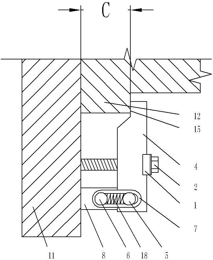
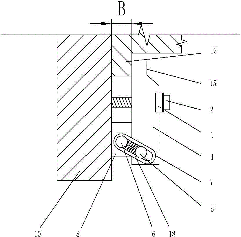
[0019] Such as Figure 1 to Figure 5 As shown, the clamping device of the injection molding machine mold includes a compression bolt 2, a clamp block 4 and a pad 8. The thickness of the pad 8 is the same as the thickness of the flange of the mold installation end, and the pad 8 is installed on the clamp block 4 and the injection molding Between the machine installation surface 11, the clamping bolt 2 passes through the clamp block 4 and presses the clamp block 4 on the mold and the cushion block 8, thereby clamping the mold on the injection molding machine installation surface 11, the cushion block 8 and the clamp block 4 is connected through the side connection block 7, the clamping block 4 and the cushion block 8 are respectively connected with the side connection block 7 through the first shaft pin 5 and the second shaft pin 6; the side connection block 7 has a waist hole 16, the first shaft pin 5, the shaft pin After the second 6 passes through the waist hole 16, it is hin...


PUM


Abstract

The invention provides a clamping device of an injection molding machine mould, and the clamping device can be used for realizing quick, safe and reliable clamping of the mould, so that the clamping efficiency of the mould can be effectively improved, tool reserve can be reduced, and the production cost can be reduced. The clamping device comprises a compaction bolt, a clamping block and a cushion block, wherein the thickness of the cushion block is same to the thickness of flange of a mould installing end, and the cushion block is installed between the clamping block and an injection molding machine installing surface in a cushioning manner; the compaction bolt penetrates through the clamping block and compacts the clamping block on the mould and the cushion block, thereby clamping the mould on the injection molding machine installing surface. The clamping device provided by the invention is characterized in that the cushion block is connected with the clamping block through a side connecting block, and the clamping block and the cushion block are respectively connected with the side connecting block through a shaft pin I and a shaft pin II.

Description

technical field [0001] The invention relates to the technical field of clamping tools for injection molding machine moulds, in particular to a clamping device for injection molding machine molds. Background technique [0002] The two sides of the mold of the injection molding machine are fixed on two opposite installation surfaces 11 in the axial direction of the injection molding machine. When clamping, the clamp block 24 is pressed tightly on the flange part 10 of the mold clamping end surface by the bolt 22 to press the mold on the mold. On the mounting surface 11, a spacer 23 with the same thickness d' and the thickness d of the flange part 10 is placed between the clamp block 24 and the mounting surface 11 to ensure that the mold is evenly stressed so as to realize reliable clamping of the mold. See Figure 6 , its disadvantage is that: because the spacer 23 and the clamping block 24 are split structures, the clamping is inconvenient and the clamping efficien...

Claims


Application Information

Patent Timeline
Patent Type & Authority Applications(China)
IPC IPC(8): B29C45/66B29C33/30B29C45/26
Inventor 的场年昭
Owner WUXI MATEX PRECISION
Learn More