Supercharge Your Innovation With Domain-Expert AI Agents!

Cover plate, and electronic equipment using same

A technology for electronic equipment and cover plate, applied in the field of electronic equipment, can solve problems such as affecting the production yield of electronic equipment, easy occurrence of air bubbles in the adhesive layer, etc., and achieve the effect of preventing air bubbles and meeting the requirements of shading

Inactive Publication Date: 2013-10-02
INTERFACE OPTOELECTRONICS SHENZHEN +1
View PDF5 Cites 4 Cited by
  • Summary
  • Abstract
  • Description
  • Claims
  • Application Information

AI Technical Summary

Problems solved by technology

Because the ink layer is usually relatively thick, the adhesive layer is often unable to fully adhere to the stepped structure formed by the edge of the ink layer, and bubbles are prone to appear, thereby affecting the production yield of electronic equipment.

Method used


Image

  • Cover plate, and electronic equipment using same
  • Cover plate, and electronic equipment using same
  • Cover plate, and electronic equipment using same

Examples


Embodiment Construction

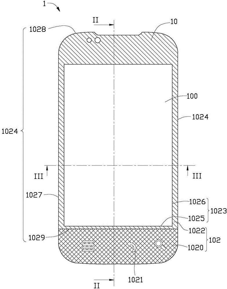
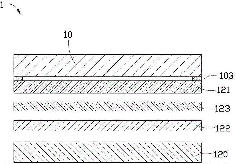
[0015] Such as Figure 1 to Figure 3 As shown, the electronic device 1 provided by the first embodiment of the present invention includes a cover plate 10 and a functional module 12 attached on the surface of the cover plate 10 . The cover plate 10 includes a display portion 100 and a non-display portion 102 . At least one button pattern 1021 is disposed on the non-display portion 102 . The display portion includes a boundary line 1023 adjacent to the non-display portion. The non-display portion 102 includes a boundary line 1024 surrounding the boundary line 1023, a first coating area 1022 defined by the boundary line 1023 and the boundary line 1024, and a second coating area covering at least the button pattern 1021. District 1020. The electronic device 1 is provided with an ink layer 103 on the surface of the cover plate 10 for attaching the functional module 12 . The ink layer 103 is disposed corresponding to the non-display portion 102 of the cover plate 10 . The thic...


PUM


Abstract

The invention provides a cover plate. The cover plate comprises a display part and a non-display part, wherein at least one key pattern is formed on the non-display part; the display part comprises a boundary line adjacent to the non-display part; the non-display part comprises a demarcation line surrounding the boundary line, a first coating area defined by the boundary line and the demarcation line, and a second coating area which at least covers the key pattern; an ink layer is coated on the non-display part; and the thickness of a part, corresponding to the second coating area, of the ink layer, is greater than the thickness of a part, corresponding to the first coating area, of the ink layer. The invention further provides electronic equipment using the cover plate.

Description

technical field [0001] The invention relates to a cover plate and electronic equipment using the cover plate. Background technique [0002] Existing electronic devices need to attach a functional panel, such as a display panel or a touch panel, to the cover plate through an adhesive layer. However, an ink layer for light-shielding is usually printed on the cover plate. Because the ink layer is usually relatively thick, the adhesive layer is often unable to fully adhere to the step structure formed at the edge of the ink layer, and bubbles are prone to appear, thereby affecting the production yield of the electronic device. Contents of the invention [0003] In view of this, it is necessary to provide a cover plate which can reduce defects caused by bonding air bubbles and an electronic device using the cover plate. [0004] A cover plate includes a display part and a non-display part. At least one button pattern is arranged on the non-display part. The display portion ...

Claims


Application Information

Patent Timeline
Patent Type & Authority Applications(China)
IPC IPC(8): B32B37/12
Inventor 韦英
Owner INTERFACE OPTOELECTRONICS SHENZHEN
Features
  • R&D
  • Intellectual Property
  • Life Sciences
  • Materials
  • Tech Scout
  • Unparalleled Data Quality
  • Higher Quality Content
  • 60% Fewer Hallucinations
Learn More