Miniature fan

A micro-fan and fan blade technology is applied to the components of the pumping device for elastic fluids, non-variable-capacity pumps, machines/engines, etc. wind effect

Active Publication Date: 2013-10-02
淮安市清江浦区市场监管综合服务中心
View PDF8 Cites 7 Cited by
  • Summary
  • Abstract
  • Description
  • Claims
  • Application Information

AI Technical Summary

Problems solved by technology

[0003] But in this way, due to the blocking of the protective net or other protective structures, the wind force of the fan

Method used


Image

  • Miniature fan
  • Miniature fan
  • Miniature fan

Examples


Embodiment Construction

[0021] The present invention will be further described below in conjunction with the accompanying drawings and preferred embodiments.

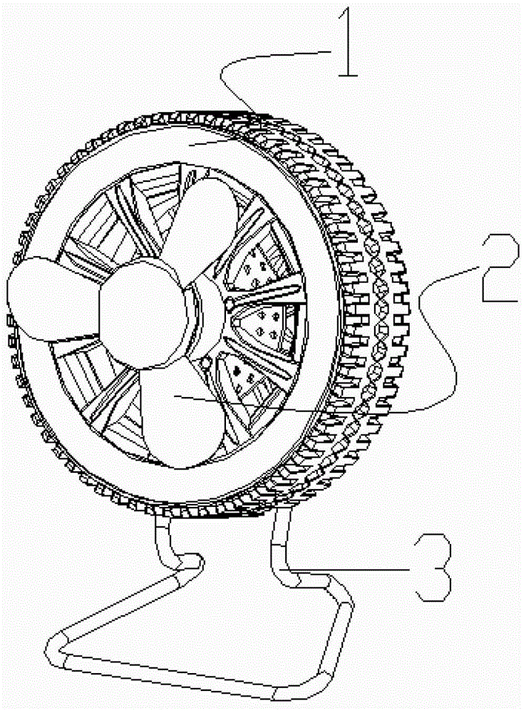
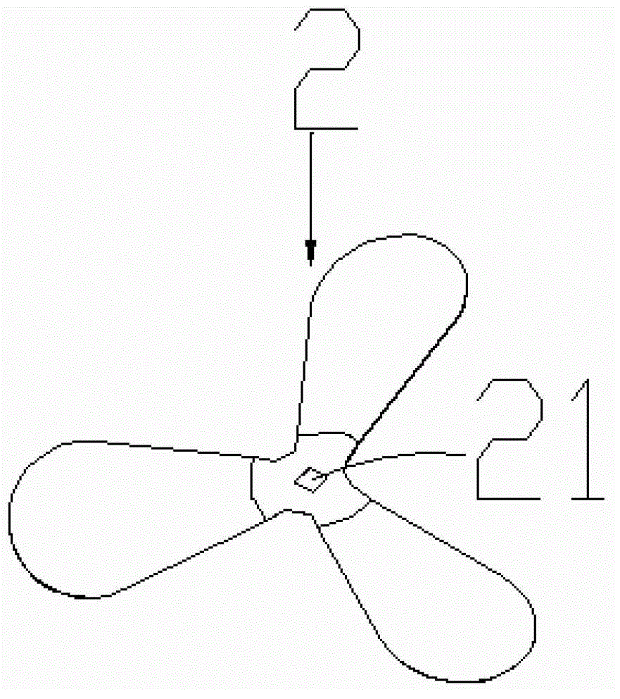
[0022] The invention discloses a micro fan, which includes a casing and a motor installed in the casing, such as Figure 1 to Figure 4 As shown, the micro fan also includes fan blades 2 made of soft materials arranged outside the housing 1 . In the present invention, since the fan blade 2 is arranged on the outside of the housing 1, the fan blade 2 will not be blocked when it rotates, so that the fan with a protective net or other protective structures relative to the fan blade 2 increases the wind force. ; and in this way, the size of the fan blade 2 can be arbitrarily set to meet the user's needs; in addition, because the fan blade 2 is made of soft material, even if the fan blade 2 is rotating, the user will not touch the fan blade 2 will be hurt.

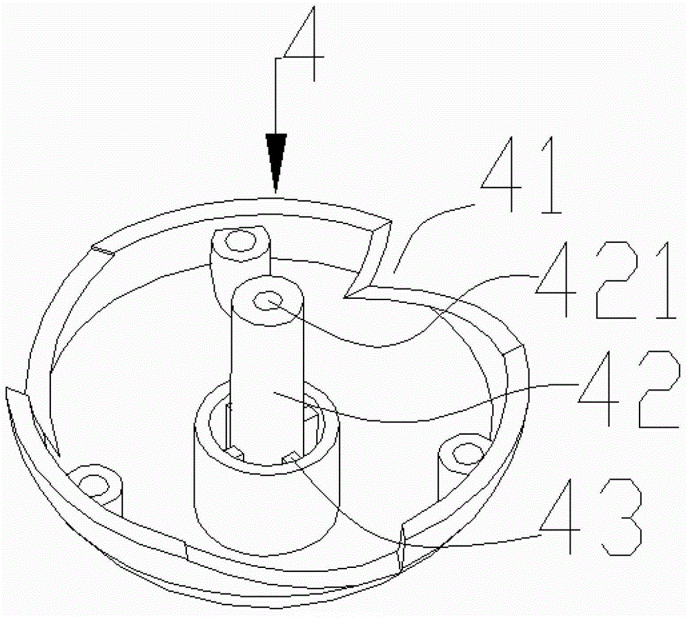
[0023] The miniature fan also includes a fixing piece for fixing the fan blade 2, the outp...


PUM


Abstract

The invention discloses a miniature fan. The miniature fan comprises a shell body, and a motor installed inside the shell body. The miniature fan further comprises fan blades arranged outside the shell body and made of soft materials. Due to the fact that the fan blades are arranged outside the shell body, the fan blades cannot be stopped in the rotation process, and therefore compared with other fans provided with the fan blades provided with protection nets or other protection structures, the miniature fan improves the wind strength. Meanwhile, the size of the fan blades can be set at will, and therefore the requirements of users are met. In addition, due to the fact that the fan blades are made of the soft materials, even when the fan blades rotate, the users can not be hurt when touching the fan blades.

Description

technical field [0001] The invention relates to the field of household electrical appliances, in particular to a miniature fan. Background technique [0002] Fans currently on the market mainly include ceiling fans and floor fans. Ceiling fans generally do not have blade protection covers, while floor fans basically have blade protection covers to avoid harming users. In order to meet people's needs, some portable micro fans have appeared in the market. Most of these micro fans are relatively small, mainly including a housing, a motor and fan blades arranged in the housing, and have a built-in battery or a rechargeable battery; The fan blades are all arranged inside the casing, and the casing is provided with an air outlet for blowing. In order to ensure safety, a protective net or other protective structures are also provided at the air outlet to prevent the fan blade from hurting the user. [0003] But in this way, due to the blocking of the protective net or other protec...

Claims


Application Information

Patent Timeline
IPC IPC(8): F04D29/34F04D29/38F04D29/52
CPCF04D29/34F04D29/382
Inventor 樊书印
Owner 淮安市清江浦区市场监管综合服务中心
Why Eureka
Try Eureka