Pipeline gas pressure measuring device

A pressure measuring device and gas technology, applied in the direction of measuring device, measuring fluid pressure, simultaneous measurement of multiple hydraulic valves, etc., can solve problems such as inability to measure accurate values, achieve the effect of improving flow state and suppressing severe impact

Active Publication Date: 2013-10-02
JIANGSU ANBANG WEIYE ARTIFICIAL ENVIRONMENT
View PDF8 Cites 14 Cited by
  • Summary
  • Abstract
  • Description
  • Claims
  • Application Information

AI Technical Summary

Problems solved by technology

The reading on the pressure gauge is to detect the air inlet pressure of each tuyere around the blast furnace circumference, but there is a certain devi

Method used


Image

  • Pipeline gas pressure measuring device
  • Pipeline gas pressure measuring device
  • Pipeline gas pressure measuring device

Examples


Embodiment Construction

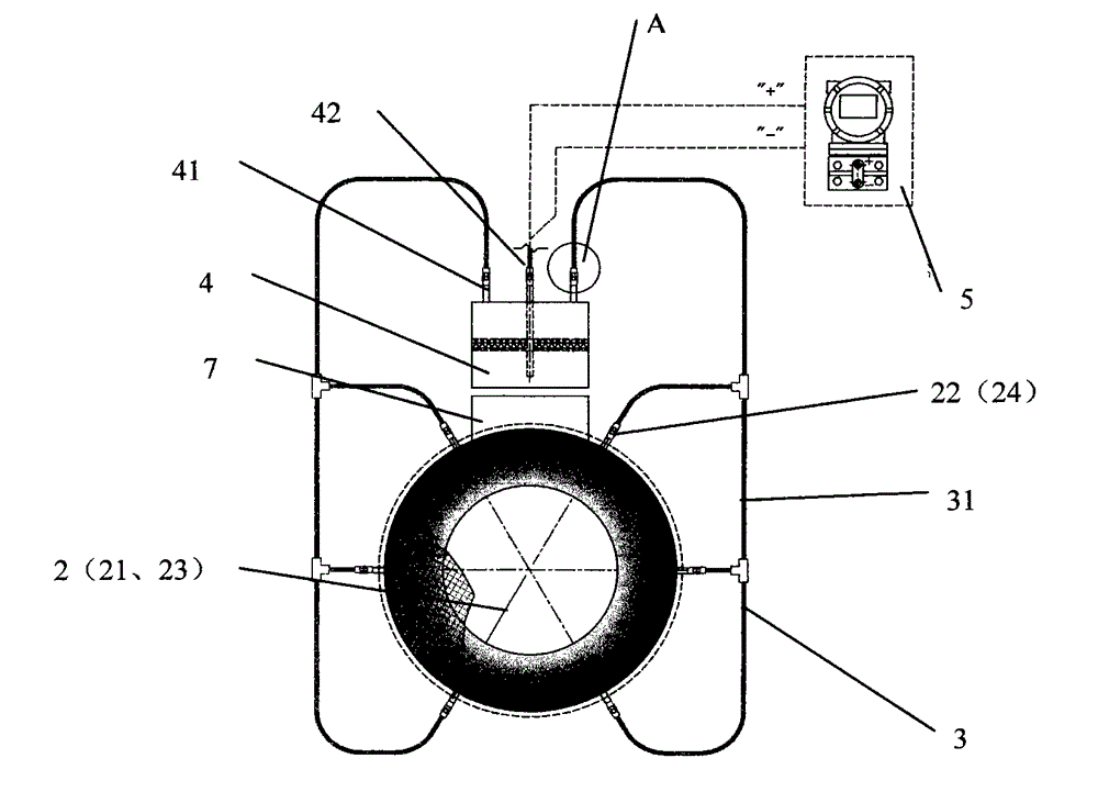
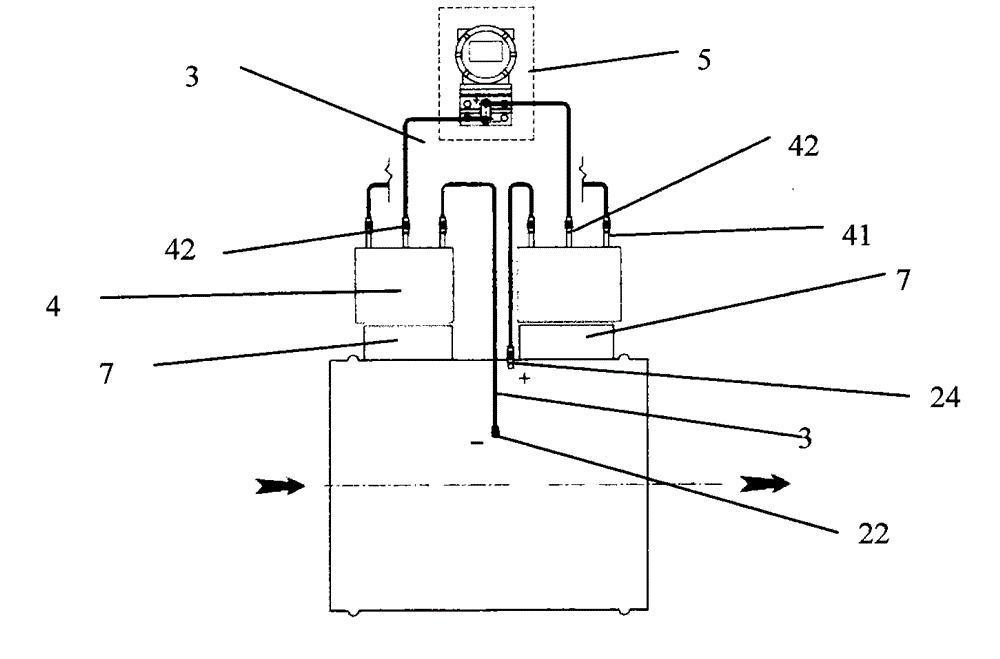
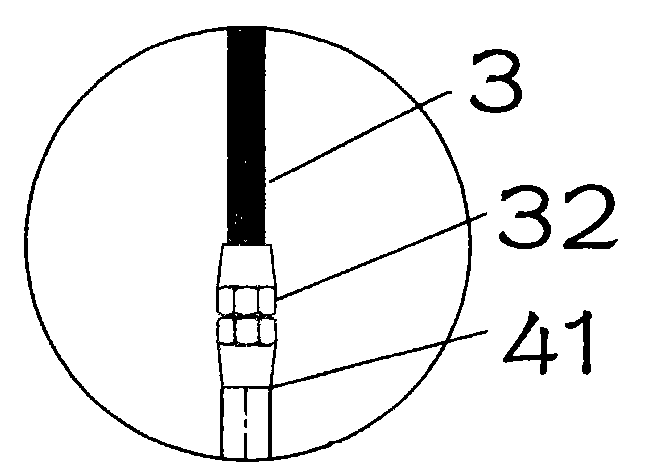
[0059] Such as figure 1 As shown, the pipeline gas pressure measuring device of the present invention is composed of a housing 1, a pressure measuring tube 2, a line pipe 3, a pressure equalizing tank 4 and a differential pressure sensor 5, wherein the housing 1 is a circular pipeline. In actual engineering, The shape of the housing is consistent with the shape of the ventilation duct. In some special cases, the ventilation duct may be square or other polygonal. The shape of the duct does not affect the use of the duct gas pressure measuring device of the present invention. The housing is embedded and fixed on the pipeline. The direction of the arrow in the figure is the flow direction of the gas in the pipeline, the position where the gas enters is the front, and the position where the gas leaves is the back.

[0060] Three pressure measuring tubes 2 are arranged radially inside the housing 1, and the pipe head 22 (24) of the pressure measuring tube 2 protrudes out of the ho...


PUM


Abstract

The invention discloses a pipeline gas pressure measuring device. The pipeline gas pressure measuring device is composed of a shell (1), one or more measuring pipes (2), a line pipe (3), one or more pressure equalizing tanks (4) and a differential pressure transducer (5), and the shell (1) is embedded in a ventilating pipeline. The pipeline gas pressure measuring device is characterized in that the shell (1) is provided with one or more measuring pipes (2) in the radial direction, the measuring pipe (2) extends out of the shell and is provided with a plurality of measuring holes; the shell is provided with one or more pressure equalizing tanks (4), an input pipe (41) of the pressure equalizing tank (4) is communicated with the pressure measuring pipe (21) through the line pipe (3), and an output pipe (42) is communicated with the differential pressure transducer (5) through the line pipe (3). The pipeline gas pressure measuring device disclosed by the utility model has the advantages of high detection precision, good stability, and ability of effectively suppressing server impacts brought about to a measuring value by random mutation pressure generated by high-speed turbulences in an air pipe.

Description

Technical field: [0001] The invention belongs to the technical field of indoor ventilation, in particular to a pipeline gas pressure measuring device for measuring gas pressure in a ventilation pipeline. Background technique: [0002] China utility model patent 200720102886.6 is a dynamic pressure measuring device for blast furnace smelting tuyeres, in order to solve the problem that no wind pressure measuring device is installed in the existing blast furnace smelting and cannot timely detect the air inlet pressure of each tuyere around the blast furnace circumference, in order to deal with the tuyere inlet pipes in time To solve the problem of blockage, a dynamic pressure measuring device for tuyeres used in blast furnace smelting is provided. The utility model adopts the following technical scheme: the device includes a pressure guiding tube which is threadedly connected with the blast furnace tuyere peephole mirror short pipe, the pressure guiding tube is provided with a ...

Claims


Application Information

Patent Timeline
IPC IPC(8): G01L15/00
Inventor 季旺良苏辉
Owner JIANGSU ANBANG WEIYE ARTIFICIAL ENVIRONMENT
Why Eureka
Try Eureka