
Electronic device, and assembly method and bonding structure of cover plate of electronic device

An electronic device and assembly method technology, applied in chemical instruments and methods, electrical digital data processing, input/output process of data processing, etc., can solve the problems of light leakage at the edge and affect the display effect, and achieve the effect of improving the display quality of the screen

Inactive Publication Date: 2013-10-02
INTERFACE OPTOELECTRONICS SHENZHEN +1
View PDF4 Cites 14 Cited by
  • Summary
  • Abstract
  • Description
  • Claims
  • Application Information

AI Technical Summary

Problems solved by technology

For example, when the touch panel of a touch mobile phone is bonded to the display module, the light in the display module may penetrate from the edge area into the visible area, resulting in the problem of light leakage at the edge when observing the screen at a large angle, which affects the display effect

Method used


Image

  • Electronic device, and assembly method and bonding structure of cover plate of electronic device
  • Electronic device, and assembly method and bonding structure of cover plate of electronic device
  • Electronic device, and assembly method and bonding structure of cover plate of electronic device

Examples


Embodiment Construction

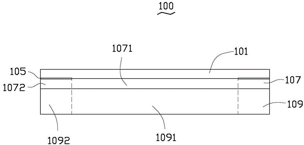
[0021] see figure 1 , the electronic device 100 may be a liquid crystal display device, a touch control device, or the like. The electronic device 100 includes a base body 109 , a first colloid 107 , a light shielding layer 105 and a cover plate 101 . The first colloid 107 is disposed on the base body 109 . The first colloid 107 has a middle region 1071 and a peripheral region 1072 disposed at the edge of the middle region 1071 . The light shielding layer 105 is disposed on the surface of the first colloid 107 away from the substrate 109 corresponding to the peripheral region 1072 . The cover plate 101 is disposed on the side of the light shielding layer 105 away from the first colloid 107 . In this embodiment, the cover plate 101 is a transparent cover plate, such as a glass cover plate. The substrate 109 can be a touch sensing film or a liquid crystal panel, etc., and includes a main functional area 1091 and a peripheral wiring area 1092 connected to the edge of the main ...


PUM


Abstract

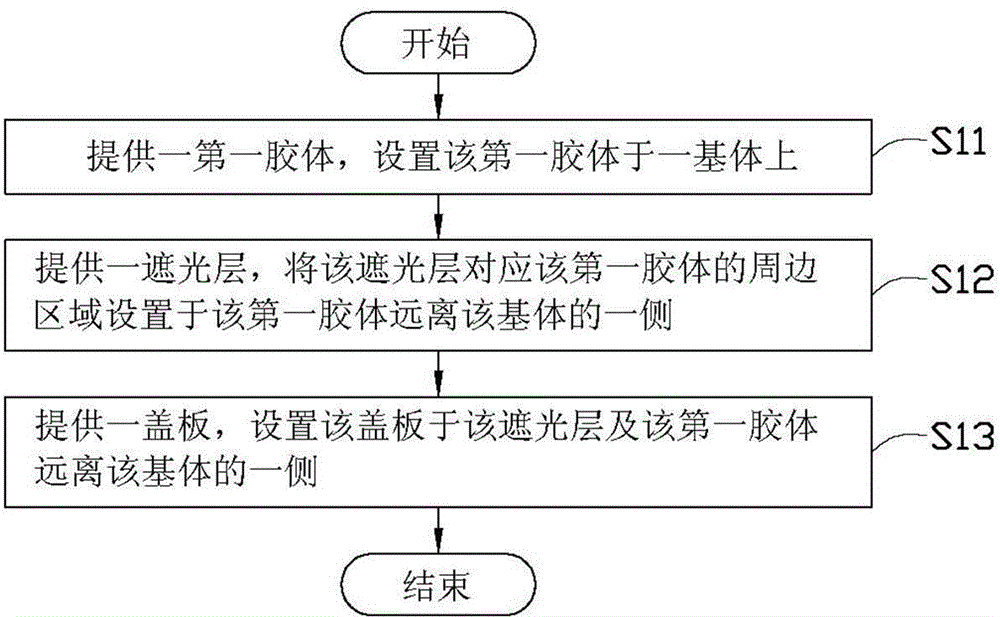
The invention relates to an electronic device, and an assembly method and a bonding structure of a cover plate of the electronic device. The assembly method comprises the following steps: providing a first colloid, and arranging the first colloid on a matrix, wherein the first colloid is provided with a middle zone and a peripheral zone arranged on the edge of the middle zone; providing a shading layer, and arranging the shading layer on the peripheral zone of the first colloid; providing the cover plate, and arranging the cover plate on the shading layer and the first colloid. Through the application of the assembly method, the shading layer can shade an edge zone of the matrix.

Description

technical field [0001] The present invention relates to an electronic device, an assembling method and a bonding structure of a cover plate of the electronic device. Background technique [0002] The phenomenon of light leakage in the edge region of electronic devices occurs from time to time. For example, when the touch panel of a touch phone is attached to the display module, the light in the display module may penetrate into the visible area from the edge area, resulting in the problem of edge light leakage when viewing the screen from a wide angle, which affects the display effect. SUMMARY OF THE INVENTION [0003] In order to solve the problem of light leakage in the edge region of the electronic device in the prior art, it is necessary to provide an assembling method, an electronic device and an adhesive structure of an electronic device cover plate with less light leakage in the edge region. [0004] A method for assembling a cover plate of an electronic device, co...

Claims


Application Information

Patent Timeline
Patent Type & Authority Applications(China)
IPC IPC(8): H05K5/03B32B27/06G06F3/041G02F1/13
Inventor 唐志舜
Owner INTERFACE OPTOELECTRONICS SHENZHEN
Learn More