Method for determining fatigue strength of engine components

A fatigue strength, engine technology, applied in the test of the engine, the test of the machine/structural component, the use of the applied stable tension/pressure to test the strength of the material, etc., can solve the problem that the matching relationship is not completely reliable

Inactive Publication Date: 2013-10-02
SCANIA CV AB
View PDF4 Cites 0 Cited by
  • Summary
  • Abstract
  • Description
  • Claims
  • Application Information

AI Technical Summary

Problems solved by technology

However, comparative tests have shown that the match between the tensile strength of test bars and the fatigue strength of engine components is not entirely reliable

Method used


Image

  • Method for determining fatigue strength of engine components
  • Method for determining fatigue strength of engine components
  • Method for determining fatigue strength of engine components

Examples


Embodiment Construction

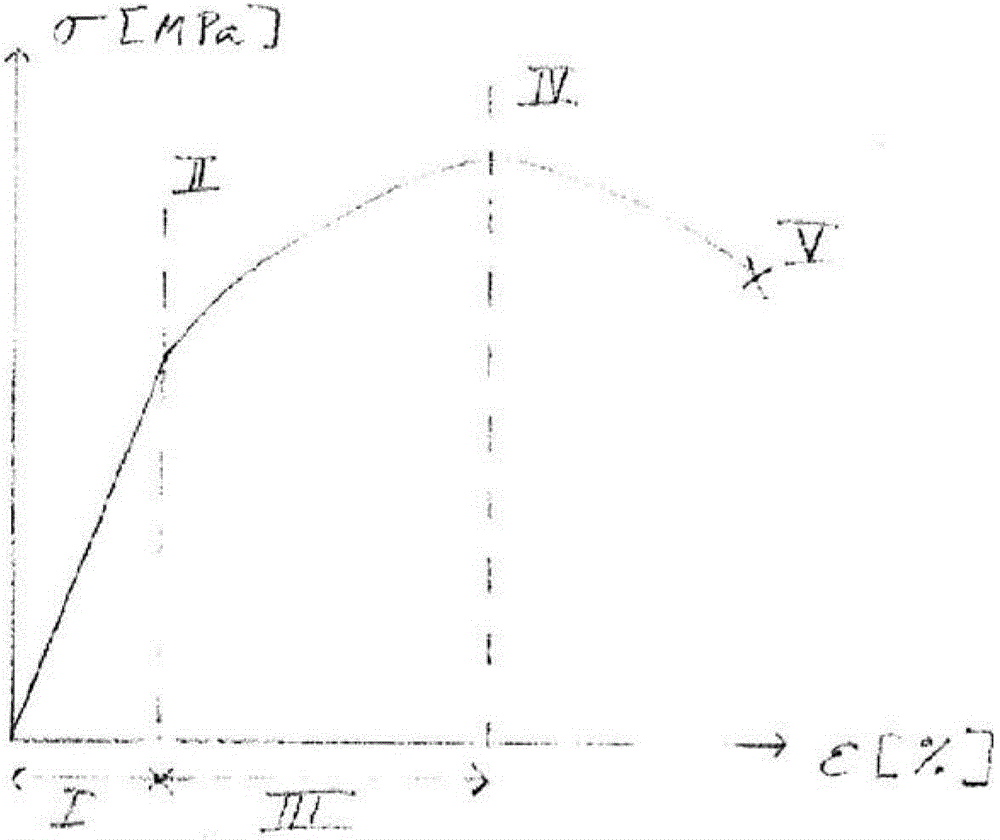
[0028] By way of introduction, the theoretical background of the invention will be referred to Figure 1a and 1b describe.

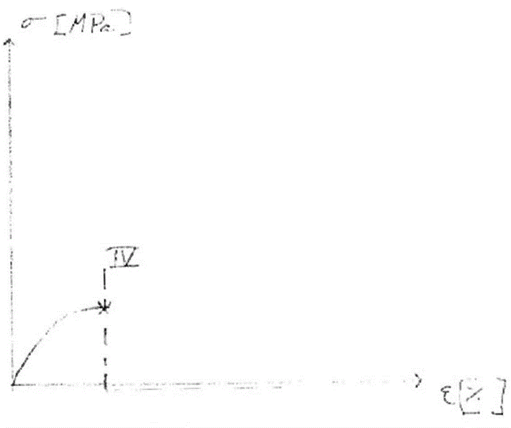
[0029] The strength of a metallic material can be represented, for example, by a stress-strain diagram based on a tensile test of a test bar. Figure 1a Schematically depicts the mode of a stress-strain diagram for a variety of metallic engineering materials, such as steel. Figure 1b The mode of the stress-strain diagram for gray iron is shown.

[0030] Figure 1a In general, a first region I is depicted in which lower forces act on the test rod. In said regions, the distance between the atoms in the material increases without affecting their mutual arrangement. If the force is removed, the test rod returns to its original dimensions. The test rod is thus elastically deformed. Said region is often referred to as the linear elastic region. If more force is applied to the test rod, the stress in the material increases. When the stress exceeds the...


PUM


Abstract

A method for determining fatigue strength of engine components, comprising the steps of -providing an engine component, -loading at least part of the component to a level below its tensile strength and measuring its resulting deformation, -determining at least one magnitude on the basis of the load applied and the deformation measured, -providing a predetermined relationship between measured fatigue strength of components and the aforesaid at least one magnitude determined on the basis of the ratio between load applied to engine components and their deformation, -determining the fatigue strength of the engine component provided,on the basis of the at least one magnitude determined and the predetermined relationship.

Description

technical field [0001] The invention relates to a method for determining the fatigue strength of engine components according to the preamble of claim 1 . Background technique [0002] Engine components, such as engine blocks and cylinder heads, are currently quality assured by cyclic fatigue testing, which subjects the engine component to repeated loading until it disintegrates. This method (see eg US4090401) is time consuming, which means that only a small proportion of components can be tested. The test method also destroys perfectly functioning components. [0003] In another method used to assure the quality of engine components, tensile testing is performed on test bars co-cast with the engine component. The failure stress of each test bar is then used as the basis for drawing conclusions about the fatigue strength of the corresponding engine component. However, comparative tests have shown that the matching relationship between the tensile strength of test bars and ...

Claims


Application Information

Patent Timeline
Patent Type & Authority Applications(China)
IPC IPC(8): G01N3/08G01M15/00
CPCG01N3/32G01N3/08G01M15/00
Inventor F·维尔贝弗斯
Owner SCANIA CV AB
Why Eureka
Try Eureka