Auxiliary jig for manipulator

A technology of manipulators and fixtures, applied in manipulators, manufacturing tools, metal processing, etc., can solve the problems of product quality, unequipped parts of products, parts easily stuck in sockets, etc., to ensure product quality and complete assembly. Effect

Active Publication Date: 2016-01-27
WUXI MATEX PRECISION
View PDF6 Cites 0 Cited by
  • Summary
  • Abstract
  • Description
  • Claims
  • Application Information

AI Technical Summary

Problems solved by technology

[0002] In the production of automatic machinery, the manipulator is used to assemble parts. In order to facilitate the manipulator to grab the parts, some smaller parts are usually placed in the auxiliary fixture. The existing auxiliary fixture has a structure such as figure 1 As shown, including the mounting plate 1, there is a socket 2 on the mounting plate 1, and the parts are inserted into the socket 2 manually. Due to the problem of the insertion method, some parts are easy to get stuck in the socket and are not easy to be taken out by the robot, resulting in The parts of some products are not equipped, and the products have serious quality problems

Method used


Image

  • Auxiliary jig for manipulator
  • Auxiliary jig for manipulator
  • Auxiliary jig for manipulator

Examples


Embodiment Construction

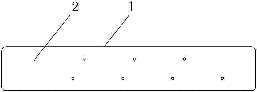
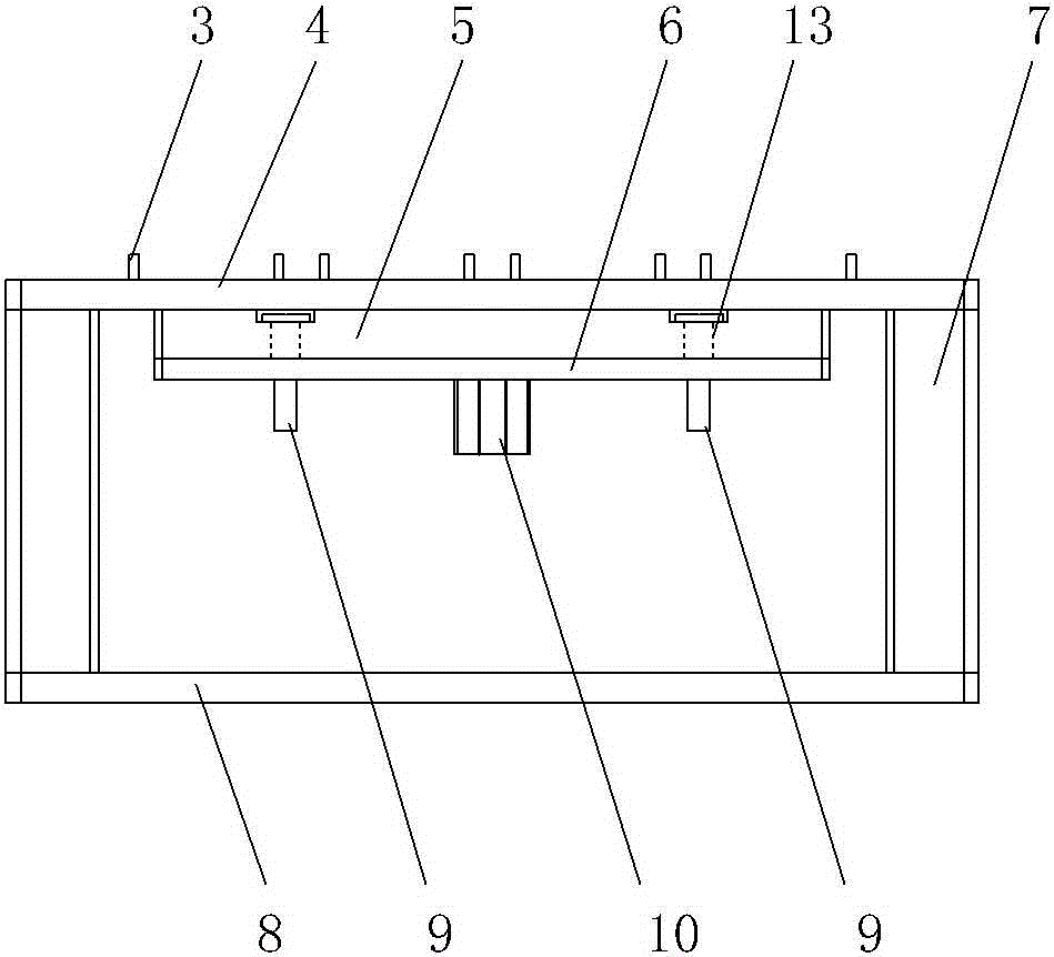
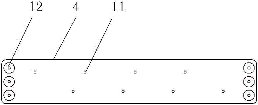
[0013] Such as figure 2 and image 3 As shown, the auxiliary jig for the manipulator includes a mounting plate. The mounting plate 4 has a socket 11, and also includes a bracket and an ejection structure. The bracket includes a support block 7 and a bottom plate 8. Side, the lateral sides of the mounting plate 4 are fixed on the two support blocks 7 of the bracket, the socket 11 is a perforation through the mounting plate 4, the ejection structure includes the top plate and the lifting drive device 10, and the lifting drive device 10 is installed on the bottom plate 8 , the top plate is fixedly connected to the output end of the lifting drive device 10, the top plate is located directly below the mounting plate 4, and is provided with a thimble 3 facing the jack, the thimble 3 moves up and down in the jack through the drive of the lifting drive device, The top plate includes a drive plate 6 and a fixed plate 5, the drive plate 6 is fixedly connected to the output end of the ...


PUM


Abstract

The invention provides an auxiliary jig used for a manipulator. By means of the auxiliary jig, the manipulator can conveniently grab a part, so a product is completely assembled, and quality of the product is guaranteed. The auxiliary jig comprises an installation plate, wherein an insertion hole is formed in the installation plate. The auxiliary jig is characterized by further comprising a support and an ejection structure. The support comprises supporting blocks and a bottom plate, and the supporting blocks are vertically installed on the two transverse sides of the bottom plate. The two transverse sides of the installation plate are fixed to the two supporting blocks of the support, and the insertion hole is a penetration hole penetrating through the installation plate. The ejection structure comprises an ejection plate and a lifting drive device, the lifting drive device is installed on the bottom plate, the ejection plate is fixedly connected with the output end of the lifting drive device, the ejection plate is located under the installation plate and is provided with an ejection pin right corresponding to the insertion hole, and the ejection pin moves upwards and downwards in the insertion hole under the drive of the lifting drive device.

Description

technical field [0001] The invention relates to the technical field of auxiliary devices for mechanical automation assembly, in particular to auxiliary fixtures for fixing parts, specifically auxiliary fixtures for manipulators. Background technique [0002] In the production of automatic machinery, the manipulator is used to assemble parts. In order to facilitate the manipulator to grab the parts, some smaller parts are usually placed in the auxiliary fixture. The existing auxiliary fixture has a structure such as figure 1 As shown, including the mounting plate 1, there is a socket 2 on the mounting plate 1, and the parts are inserted into the socket 2 manually. Due to the problem of the insertion method, some parts are easy to get stuck in the socket and are not easy to be taken out by the robot, resulting in The parts of some products are not equipped, and the products have serious quality problems. Contents of the invention [0003] In view of the above problems, the ...

Claims


Application Information

Patent Timeline
Patent Type & Authority Patents(China)
IPC IPC(8): B23P19/00B25J19/00
Inventor 的场年昭
Owner WUXI MATEX PRECISION
Why Eureka
Try Eureka