AI technical title is built by Patsnap AI team. It summarizes the technical point description of the patent document.
A technology of time measurement and clock, which is applied in the field of computers, can solve the problem of low measurement time accuracy and achieve the effect of improving the signal-to-noise ratio and measurement time accuracy
Inactive Publication Date: 2013-10-09
NEUSOFT MEDICAL SYST CO LTD
View PDF5 Cites 8 Cited by
Summary
Abstract
Description
Claims
Application Information
AI Technical Summary
This helps you quickly interpret patents by identifying the three key elements:
Problems solved by technology
Method used
Benefits of technology
Problems solved by technology
[0005] In order to solve the above-mentioned technical problem of low measurement time accuracy in PET, the present invention provides a time measurement method and device
Method used
Image
Click on the blue label to locate the original text in one second.
Reading with bidirectional positioning of images and text.
Examples
Embodiment 1
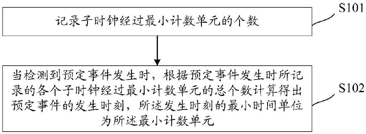
[0036] see figure 1 , it is the method flowchart of a kind of time measurement method of the present invention, is applied in FPGA (Field-ProgrammableGateArray, Field Programmable Gate Array), and this method comprises setting stage:
[0037] Convert the input clock of the FPGA into N sub-clocks, and the period of each sub-clock is M, where the quotient of M divided by N is the minimum counting unit for time measurement;
[0038] Adjust the phase difference between adjacent sub-clocks to L according to the number N of sub-clocks, where L is the quotient of dividing 360° by N;
[0039] Preferably, the input clock of the FPGA is converted into N sub-clocks, and the period of each sub-clock is M, wherein the quotient of M divided by N is the minimum counting unit for time measurement and is specifically:
[0040] The input clock of FPGA is converted into 20 sub-clocks, and the period of each sub-clock is 2.5ns, wherein, the quotient of dividing the period of each sub-clock of 2....
Embodiment 2
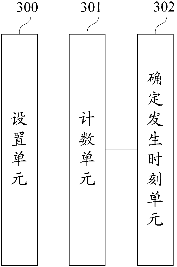
[0062] Corresponding to the above-mentioned time measuring method, an embodiment of the present invention further provides a time measuring device. see image 3 , which is a device structure diagram of a time measuring device according to the present invention, which includes a setting unit 300 , a counting unit 301 and a unit 302 for determining the time of occurrence.
[0063] The setting unit 300 is used to convert the input clock of the FPGA into N sub-clocks, and the period of each sub-clock is M, wherein the quotient of M divided by N is the minimum counting unit for time measurement; according to the number N of the sub-clocks, the phase The phase difference between adjacent sub-clocks is adjusted to L, where L is the quotient of 360° divided by N;
[0064] Preferably, the setting unit is specifically:
[0065] The input clock of FPGA is converted into 20 sub-clocks, and the period of each sub-clock is 2.5ns, wherein, the quotient of dividing the period of each sub-cl...
PUM
Abstract
The invention discloses a time measurement method and device which are applied to an FPGA. An input clock is converted to N sub clocks, and the period of each sub clock is M, wherein the quotient obtained by dividing M with N is the smallest counting unit for time measurement; the phase difference between every two adjacent sub clocks is adjusted to be L, wherein L is the quotient obtained by dividing 360 degrees with N; when timing is started, the number of the smallest counting units which the sub clocks pass through is recorded; when occurrence of a preset event is detected the total number of the smallest counting units which the sub clocks pass through is recorded to calculate the occur moment of the preset event, and the smallest time unit of the occur moment is the smallest counting unit. Therefore, through the method that the input clock of an FPGA chip is adjusted to form a plurality of sub clocks with the same period and the phase difference between every two adjacent sub clocks is correspondingly adjusted, the smallest counting unit of the FPGA can be increased, and the technical effect that the time measurement precision of a PET system is improved is achieved.
Description
technical field [0001] The invention relates to the field of computers, in particular to a time measuring method and device. Background technique [0002] PET (Positron Emission Tomograph, Positron Emission Tomography) is a computed tomography device based on the positronannihilationradiation generated during the decay of radionuclides injected into the body and in accordance with the detection principle. PET imaging is a "nuclide tracer imaging technology". PET imaging first needs to inject biotracer drugs synthesized by radionuclides that can release positrons in the patient's body, and then conduct further analysis by detecting the location of the annihilation reaction of radionuclides. [0003] The specific annihilation process is that biotracers are usually proton-rich nuclides that generate positrons during their decay. The positrons emitted by the radionuclides injected into the body will combine with the negative electrons in the human body to produce annihilatio...
Claims
Application Information
Patent Timeline
Application Date:The date an application was filed.
Publication Date:The date a patent or application was officially published.
First Publication Date:The earliest publication date of a patent with the same application number.
Issue Date:Publication date of the patent grant document.
PCT Entry Date:The Entry date of PCT National Phase.
Estimated Expiry Date:The statutory expiry date of a patent right according to the Patent Law, and it is the longest term of protection that the patent right can achieve without the termination of the patent right due to other reasons(Term extension factor has been taken into account ).
Invalid Date:Actual expiry date is based on effective date or publication date of legal transaction data of invalid patent.

