Method and device for identifying signal light

A recognition method and signal lamp technology, applied in character and pattern recognition, image data processing, instruments, etc., can solve problems such as the influence of recognition distance, slow detection speed, and increase the processing capacity of shape detection, so as to improve the accuracy of determination and reduce Quantity, the effect of improving processing speed and accuracy

Active Publication Date: 2013-10-09
NEUSOFT REACH AUTOMOTIVE TECH SHANGHAI CO LTD
View PDF2 Cites 52 Cited by
  • Summary
  • Abstract
  • Description
  • Claims
  • Application Information

AI Technical Summary

Problems solved by technology

This is mainly because in addition to signal lights, there will be many background colors in the image that match the predefined colors, for example, red or yellow vehicles, green billboards, red buildings, green bus stop signs, etc., These may be selected as signal light candidate areas, which will inevitably increase the processing capacity of subsequent shape detection, affect the processing speed of shape detection, and then affect the speed of signal light self-detection, and the timeliness is poor
[0007] (2) May produce over-segmentation
[0009] There may be the following problems in this process: the signal light must be in the middle and short distance, if the signal light is too far away from the camera device, the mask used in the detection process will not be able to determine the desired point
In addition, the distance between the camera device and the signal light will also affect the imaging effect and imaging size of the signal light in the image. In this way, when performing shape detection, it is necessary to use templates of different sizes to try to match with the signal light candidate area, which will reduce the The efficiency of shape detection takes a long time and is also not time-sensitive
[0010] To sum up, the automatic detection method of signal lights in the prior art has slow detection speed and poor timeliness, and may even fail to accurately identify signal lights. In addition, this method is also seriously affected by the recognition distance and background color

Method used


Image

  • Method and device for identifying signal light
  • Method and device for identifying signal light
  • Method and device for identifying signal light

Examples


Embodiment Construction

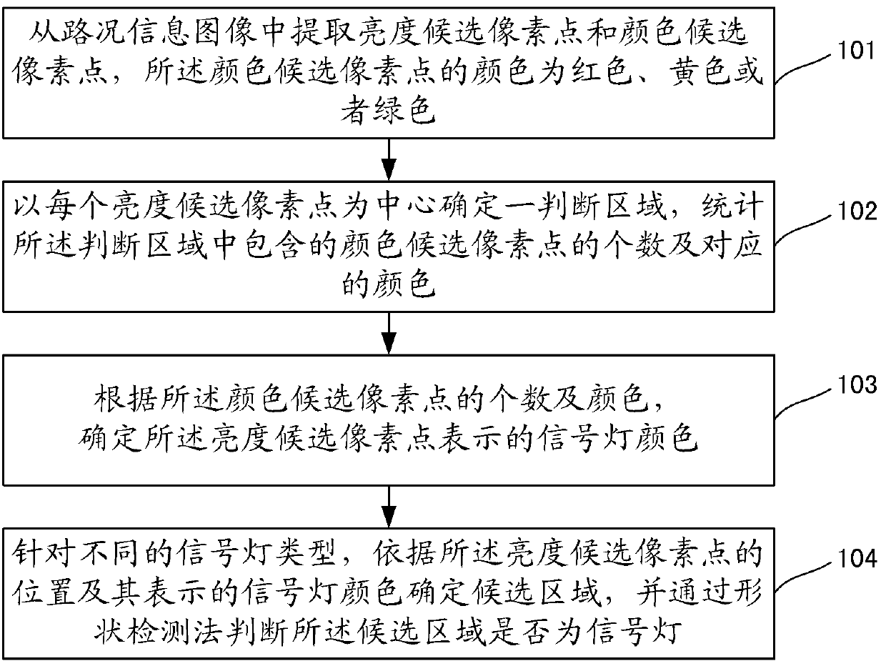
[0061] In order to enable those skilled in the art to better understand the solution of the present invention, the embodiments of the present invention will be further described in detail below in conjunction with the accompanying drawings and implementation manners.

[0062] Firstly, the application scenarios of the technical solutions of the present invention are introduced.

[0063] With the progress and development of traffic, road traffic accidents have become one of the global safety issues, which has attracted the attention of the whole society and people. According to statistics in recent years, people are the main factor causing traffic accidents, and the lack of concentration of drivers is an important reason for frequent traffic accidents. Therefore, it is very necessary to develop intelligent vehicles to increase traffic safety. Intelligent vehicle technology is mainly divided into two aspects: assisted driving and automatic driving. The automatic detection and rec...


PUM


Abstract

The invention discloses a method and device for identifying a signal light. The method for identifying the signal light includes the following steps: a, extracting candidate luminance pixels and candidate color pixels from a traffic information image, wherein the color of the candidate color pixels is red or yellow or green; b, confirming judgment areas with the candidate luminance pixels as centers, counting the number of the candidate color pixels in the judgment areas and confirming the corresponding color of the candidate color pixels in the judgment areas, c, confirming the color of the signal lights which are represented by the candidate luminance pixels according to the number and the color of the candidate color pixels, d, aiming at the types of the different signal lights, confirming candidate areas according to the positions of the candidate luminance pixels and the color of the signal lights which are represented by the candidate luminance pixels, and judging whether the candidate areas are the signal lights through a shape detection method. By means of the method for identifying the signal light, the signal light candidate areas are confirmed with the combination of luminance factors and color factors, the number of finally confirmed candidate areas is reduced, the confirming accuracy of the candidate areas is improved, and thus the processing speed and accuracy of the follow-up shape detection process are improved.

Description

technical field [0001] The invention relates to the technical field of traffic control, in particular to a signal lamp identification method and device. Background technique [0002] In order to ensure the safety of vehicles during driving, more and more smart vehicles begin to pay attention to the automatic detection and recognition function of traffic lights during vehicle driving. At present, the automatic detection method of signal lights is realized on the basis of color segmentation and shape detection, and the scheme can be briefly described as follows: [0003] First, the image of the road condition information in front of the vehicle is captured by the camera installed on the vehicle; [0004] Secondly, the color segmentation method is used to select the area that matches the predefined color in the image as the signal light candidate area. This process can be realized by color lookup table or color space threshold segmentation method. [0005] The following prob...

Claims


Application Information

Patent Timeline
Patent Type & Authority Applications(China)
IPC IPC(8): G06T7/40G06K9/00
Inventor 刘威王豪袁淮
Owner NEUSOFT REACH AUTOMOTIVE TECH SHANGHAI CO LTD
Why Eureka
Try Eureka