
Power converter

A technology for power converters and shells, which is applied to circuits, electrical components, contact parts, etc., can solve problems such as cutting corners, safety hazards, and structural design errors, and achieve the effects of reducing use costs, reducing safety hazards, and prolonging service life

Active Publication Date: 2013-10-09
徐州新电高科电气有限公司
View PDF4 Cites 0 Cited by
  • Summary
  • Abstract
  • Description
  • Claims
  • Application Information

AI Technical Summary

Problems solved by technology

[0003] During the use of various power converters, the reasons for short circuit, sparking, heating and electric shock accidents are poor material, cutting corners, structural design problems and wrong use methods. The key problem is the live wire, neutral wire, ground wire The unscientific design of the gap and creepage distance between the terminals and the wiring, and the unreasonable design of the plug-in sleeve are caused by the current commercially available power converters produced according to national standards, even if the material and size meet the quality requirements, but due to The congenital defect of sleeve design, when the pin of the plug is inserted into the power socket, most of them are in the form of local point contact or local line contact. When the carrying capacity is insufficient, heating or sparking will inevitably occur, especially in power conversion. After long-term use, the metal surface of the socket is oxidized, worn, and deformed, and it is more likely to cause poor contact. Therefore, there are serious safety hazards in various power converters in the prior art.

Method used


Image

  • Power converter
  • Power converter
  • Power converter

Examples


Embodiment Construction

[0014] The present invention will be further described below in conjunction with the accompanying drawings.

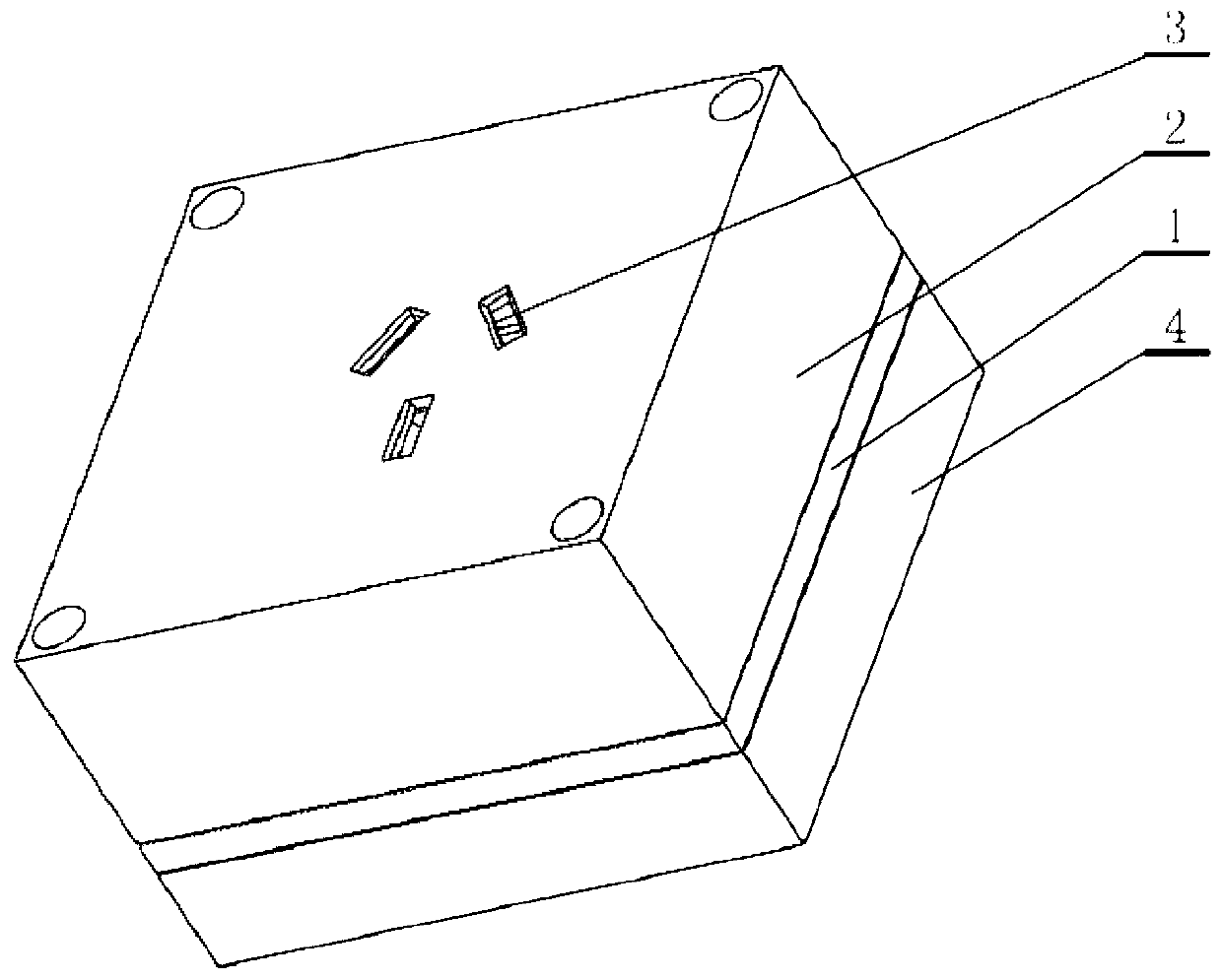
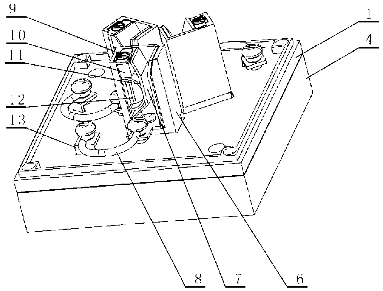
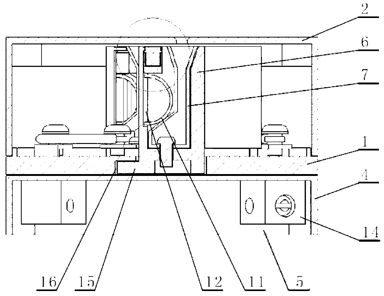
[0015] Such as Figure 1 to Figure 4 As shown, the power converter includes a middle case 1, and an upper case 2 and a lower case 4 installed in cooperation therewith. The middle case 1 is screwed to a bottom plate 5, and the terminal 14 passes through the middle case 1 and the bottom plate. 5. It is airtightly packaged in the lower case 4, and the connecting terminal 14 is reliably connected to the intermediate connecting terminal 13; figure 1 As shown, an insertion hole 3 is provided at the position corresponding to the socket on the upper housing 2 .

[0016] A chute 16 is provided between the middle housing 1 and the lower housing 4, and the sleeve bracket 6 is installed in the chute 16 through the slider 15, and the sleeve bracket 6 passes through the action of the slider 15 and the chute 16, With the change of the center distance error of the power plug blades,...


PUM


Abstract

The invention discloses a power converter. A sliding slot (16) is arranged between a middle shell body (1) and a lower shell body (4). A plug bush support (6) is mounted in the slide slot through a sliding block (15). An integral-type plug bush (7) is mounted in the plug bush support. A pressure-regulating sliding slot (12) is arranged in the plug bush support. A pressure-regulating elastic sheet (11) and pressure-regulating sliding blocks (10) are mounted in the pressure-regulating sliding slot, wherein the pressure-regulating sliding blocks are connected through pressure regulating screws (9). Compared with the prior art, the power converter achieves the effect that a plug sheet and a plug bush of a plug are in surface contact, can increase the current carrying capacity of a current carrying body substantially, avoids the accidents such as a fire and an electric shock caused by heating, ignition and other phenomena which happen due to the fact that the plug is in poor contact with a socket, and reduces the occurrences of potential safety hazards; meanwhile, the effect that the plug bush can be repaired through the adjustment of the pressure of the elastic sheet when the plug bush is seriously worn or the elasticity of the plug bush is lowered after the plug bush is used for a long term, therefore, the service life of the power converter is prolonged, the use cost is lowered, and resources are saved.

Description

technical field [0001] The invention relates to a power converter and belongs to the technical field of power conversion socket safety protection. Background technique [0002] At present, all kinds of power converters (that is, power sockets) are small electrical materials necessary for people's life. Although the objects are small and of low value, they are directly related to the safety of people's personal and property. According to the statistics of relevant departments, among the fire accidents that have occurred in my country in the past 10 years, electric shocks and fires caused by power sockets and short circuits of switches rank first among all kinds of fire accidents, and nearly 80% of urban and rural residential fires are related to fire accidents. The power outlet is faulty or the line is broken. It can be seen that the safety protection quality of the power converter is directly related to people's home safety. [0003] During the use of various power converte...

Claims


Application Information

Patent Timeline
Patent Type & Authority Applications(China)
IPC IPC(8): H01R13/502H01R13/631H01R13/40H01R13/18
Inventor 邓建华冯仰怀
Owner 徐州新电高科电气有限公司
Learn More