Signal processing method and circuit and led dimming circuit with the circuit

A signal processing and signal technology, applied in the field of electronics, can solve the problems of slow circuit response, capacitors that cannot be integrated inside the chip, and miniaturized integrated circuits that cannot be realized.

Active Publication Date: 2018-05-29
SILERGY SEMICON TECH (HANGZHOU) CO LTD
View PDF6 Cites 0 Cited by
  • Summary
  • Abstract
  • Description
  • Claims
  • Application Information

AI Technical Summary

Problems solved by technology

[0006] In this case, it is difficult to integrate resistors and capacitors with large resistance and capacitance in the chip, especially when the capacitance of the capacitor is large, the capacitor cannot be integrated in the chip
Moreover, at this time, the response speed of the RC filter circuit is slow, and it often takes several cycles to respond to the information of the dimming signal, resulting in the inability to realize a miniaturized integrated circuit, and there is a problem of slow response speed of the circuit.

Method used


Image

  • Signal processing method and circuit and led dimming circuit with the circuit
  • Signal processing method and circuit and led dimming circuit with the circuit
  • Signal processing method and circuit and led dimming circuit with the circuit

Examples


Embodiment 1

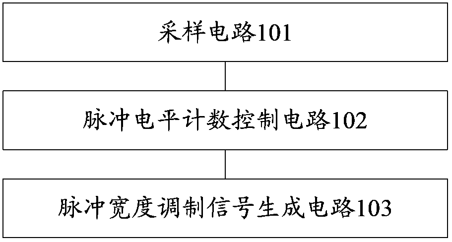
[0086] This embodiment provides a signal processing circuit, which mainly includes a sampling circuit 101 , a pulse count control circuit 102 , and a pulse width modulation signal generation circuit 103 .

[0087] Wherein, the input end of the sampling circuit 101 is connected to the first pulse width modulation signal and the first clock signal input from the outside, the output end is connected to the input end of the pulse count control circuit 102, and the output end of the pulse count control circuit 102 is connected to the pulse width modulation The input terminal of the signal generating circuit 103 is connected. Its circuit works as follows:

[0088] The sampling circuit 101 samples the first pulse width modulation signal according to the frequency of the first clock signal, obtains the sampling pulse, and obtains the number of sampling pulses corresponding to the high level within one cycle of the first pulse width modulation signal within the sampling pulse (hereina...

Embodiment 2

[0103] As a schematic illustration of the signal processing circuit of this embodiment, the following will schematically describe this embodiment with regard to the implementation manner of a specific application circuit of this embodiment.

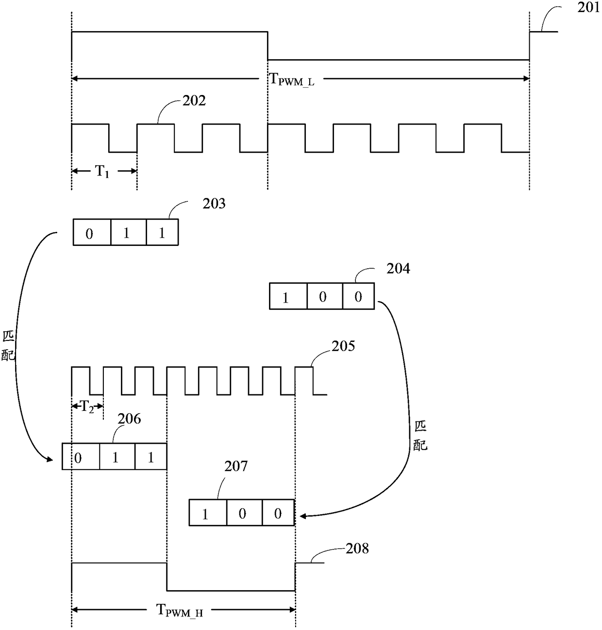
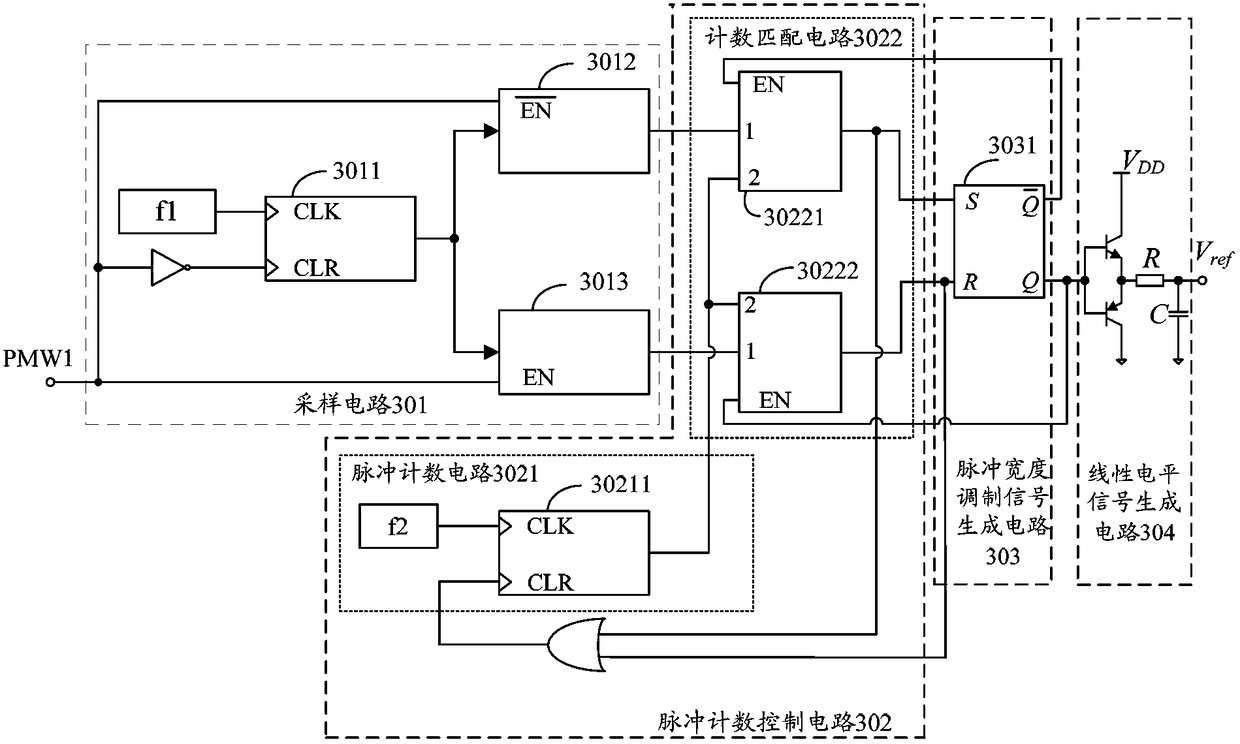
[0104] see image 3 As shown, in this embodiment, the sampling circuit 301 can be composed of, but not limited to, the following circuit structure.

[0105] The sampling circuit 301 includes: a first counter 3011 , a second counter 3012 and a third counter 3013 . Wherein, the input terminals of the first counter 3011 are connected to the first pulse width modulation signal PMW1 and the first clock signal f1 respectively, and the output terminals are respectively connected to the signal input terminals of the second counter 3012 and the third counter 3013 . It works as follows:

[0106] The clock input terminal "CLK" of the first counter 3011 is connected to the first clock signal f1, and the clearing control terminal "CLR" is connected ...

Embodiment 3

[0129] see Figure 4 As shown, this embodiment provides a signal processing method, which mainly includes the following steps:

[0130] Step 401: Sampling the first PWM signal at a low frequency to obtain a sampling pulse.

[0131] According to the frequency of the first clock signal with a lower frequency, the first pulse width modulation signal is sampled to obtain a sampling pulse.

[0132] In the same way as in Embodiment 2, in this embodiment, three counters can also be used to sample the number of high-level sampling pulses and the number of low-level sampling pulses of the sampling pulses in a first pulse width modulation signal cycle. . For example, the cooperation process of three counters is as follows:

[0133] S1: The first counter samples the first pulse width modulation signal according to the frequency of the first clock signal, outputs the sampling pulse, and inputs the sampling pulse to the second counter and the third counter respectively.

[0134] S2: Th...


PUM


Abstract

The invention relates to the field of electronics, and discloses a signal processing method, a circuit and an LED dimming circuit with the circuit. The method includes: sampling the first pulse width modulation signal according to the frequency of the first clock signal, obtaining sampling pulses, and counting the number of pulses of the second clock signal from zero until the current cumulative number of pulses is consistent with the number of high-level sampling pulses Until now, store the current cumulative number of pulses as the first pulse number, and output the first pulse signal; count the number of second clock signal pulses from zero until the current cumulative number of pulses is consistent with the number of low-level sampling pulses So far, the current accumulated pulse number is stored as the second pulse number, the second pulse signal is output, and the second pulse width modulation signal is generated according to the first pulse signal and the second pulse signal. The application of this technical solution is beneficial to increase the frequency of the PMW signal while keeping its duty cycle unchanged, and realize the miniaturization and integration of the circuit under the condition of low modulation frequency.

Description

technical field [0001] The invention relates to the field of electronics, in particular to a signal processing method and circuit and an LED dimming circuit with the circuit. Background technique [0002] In LED lighting applications, pulse width modulation (Pulse Width Modulation, PWM for short) signals are mostly used as dimming signals to adjust the luminance of LEDs. The dimming process of the LED by using the PWM signal is mainly to convert the information of the duty ratio in the PWM signal into a linear level signal, thereby simulating the linear output of the LED. [0003] The LED dimming circuit in the prior art is mainly implemented by a first-order RC filter circuit, and the cut-off frequency f of the filter circuit is c is: 1 / 2πRC, where the cut-off frequency f of the filter circuit is required c Less than the dimming frequency of the PWM signal, that is, the cut-off frequency f c The smaller the value, the larger the required parameter R*C should be. [0004...

Claims


Application Information

Patent Timeline
Patent Type & Authority Patents(China)
IPC IPC(8): H05B37/02H05B44/00
CPCH05B45/10Y02B20/30Y02B20/40
Inventor 韩云龙陈惠强
Owner SILERGY SEMICON TECH (HANGZHOU) CO LTD
Why Eureka
Try Eureka