A kind of removal

A technology for removing awning machines and racks, which is applied in agricultural machinery and implements, threshing equipment, applications, etc., can solve the problems of difficulty in wind adjustment, incomplete removal of impurities, and difficulty in cleaning internal and external drums, and achieves ideal awn removal effect.

Active Publication Date: 2016-03-09
XINJIANG TIANYE GRP
View PDF8 Cites 0 Cited by
  • Summary
  • Abstract
  • Description
  • Claims
  • Application Information

AI Technical Summary

Problems solved by technology

[0004] CN2213566Y discloses an internal and external differential drum awning cleaning machine, the main structure of which is the combined design of the differential drum 1 and the suspension cleaner 7, but the wind cleaning adopted by the suspension cleaner of this equipment is not suitable for rice. It is not suitable for the seeds of relatively light crops, and it is difficult to adjust the wind force. If it is too large, it will easily bring the seeds into the impurities.
[0005] 201210280394.1 discloses a kind of awning machine for rice seeds, which mainly stirs the rice seeds through the agitation mechanism arranged in the tank body, makes the seeds rub against each other, and removes the awns and the seed hairs attached to the seed coat, so as to achieve a smooth surface of the seeds, but The rice seeds and other impurities of this equipment are collected through the same outlet, and they must be cleaned by other equipment before they can be used for mechanical direct seeding.

Method used


Image

  • A kind of removal
  • A kind of removal
  • A kind of removal

Examples


Embodiment Construction

[0026] The present invention will be described in detail below in conjunction with the accompanying drawings. The description in this part is only exemplary and explanatory, and should not have any limiting effect on the protection scope of the present invention.

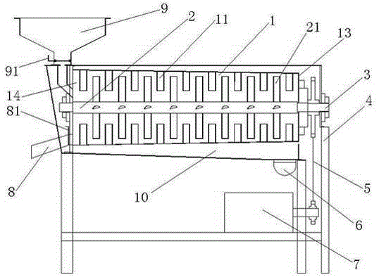
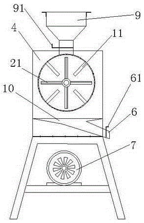
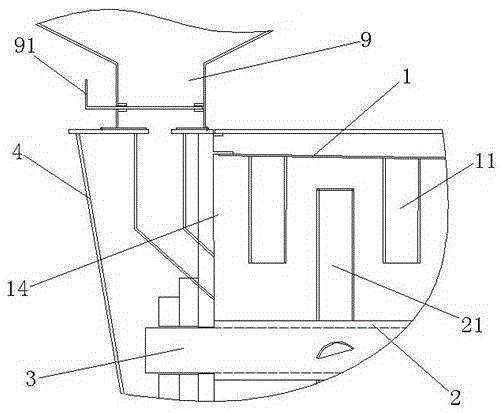
[0027] Such as Figure 1-4 The awning machine shown includes a frame 4, a drive motor 7 installed at the bottom of the frame 4, a stirring drum 1 and a central shaft 3 installed inside the upper part of the frame 4, and a stirring drum set outside the central shaft 3. axis 2;

[0028] The two ends of the central shaft 3 are respectively matched with the frame 4 through bearings, and one end passing through the closed end 13 of the stirring drum 1 is fixedly connected with the stirring drum 1 and the transmission device 5;

[0029] The fixed end of the stirring shaft 2 passes through the open end 14 of the stirring drum 1 and is fixed on the frame 4, along the axial direction of the stirring shaft 2, there are sever...


PUM


Abstract

The invention discloses an awner which comprises a rack, a drive motor, a stirring roller, a center shaft and a stirring shaft, wherein the drive motor is installed on the lower portion of the rack. The stirring roller and the center shaft are installed inside the upper portion of the rack. The stirring shaft is sleeved outside the center shaft. The two ends of the center shaft are respectively matched with the rack through a bearing. The center shaft penetrates through one sealed end of the stirring roller and is fixedly connected with the stirring roller and a transmission device. The fixed end of the stirring shaft penetrates through the open end of the stirring roller and is fixed on the rack. A plurality of stopping rods which extend in the radial direction of the stirring shaft are evenly distributed in the axial direction of the stirring shaft. A plurality of stirring rods are evenly distributed on the inner wall of the stirring roller, wherein the stirring rods and the stopping rods are staggered. A plurality of through holes are distributed in the roller wall of the stirring roller. A discharge port which is communicated with the inner portion of the stirring roller is formed in the lower portion of one side, arranged at the open end of the stirring roller, of the rack. A feed port which is communicated with the inner portion of the stirring roller is formed in the upper portion of one side, arranged at the open end of the stirring roller, of the rack. An impurity collecting groove is formed below the stirring roller, and an impurity discharge port is formed at the bottom of the impurity collecting groove. The awner is suitable for large-scale awn removing operation, ideal in effect, and capable of enabling awns to be separated from seeds directly and eliminated.

Description

technical field [0001] The invention relates to the technical field of awning equipment, in particular to an awning machine. Background technique [0002] Due to the spontaneous traits of rice seeds, there are about 5 mm awns that are 1 to 2 times larger than the seeds, and the seeds have short hairs on the epidermis, and are relatively astringent. Due to the existence of this trait in the seeds, the seeds are blocked by each other in mechanized sowing , It is impossible to realize the requirements of large-scale mechanized live broadcast and precise planting, resulting in uneven planting and uneven emergence after sowing. [0003] CN1430871A discloses a small-sized automatic dehorning device for rice seeds. The dehorning device adopts the tooth beds of concave-convex rubber dehorning teeth that mesh with each other on the upper and lower sides to generate friction to achieve dehorning and other purposes. However, it is not suitable for awning operations on rice seeds of a ...

Claims


Application Information

Patent Timeline
Patent Type & Authority Patents(China)
IPC IPC(8): A01F12/42
Inventor 陈林周鑫王永强李高华彭文捷刘小武陈伊锋
Owner XINJIANG TIANYE GRP
Why Eureka
Try Eureka