a fertilizer machine

A fertilizer mixing machine and frame technology, applied in mixers, mixer accessories, mixers with rotating mixing devices, etc., can solve the problems of unstable operation, increased floor space, height, etc., to reduce process control points, Ensure stable operation and avoid error-prone effects

Active Publication Date: 2016-01-20
和原生态控股股份有限公司
View PDF5 Cites 14 Cited by
  • Summary
  • Abstract
  • Description
  • Claims
  • Application Information

AI Technical Summary

Problems solved by technology

[0002] In order to make the crops grow better, it is often necessary to fertilize them, and because the types of crops and their growth environments are different, the requirements for fertilizers are also different, so there is a fertilizer machine; the commonly used fertilizer The machine is divided into small-scale fertilizer distribution machine and large-scale fertilizer distribution machine. The existing small-scale fertilizer distribution machine transports different fertilizers to different storage bins by the lifting mechanism and transportation device, and then the storage bin passes the quantitative fertilizer through the feeder Discharging, the collecting device collects the discharged fertilizer, transports it to the mixing device for stirring, and finally discharges the package to complete the fertilizer mixing process, but because the small fertilizer mixing machine needs to transport the fertilizer multiple times, it increases the cost of fertilizer mixing The process control point makes the small fertilizer distributing machine have high failure rate, unstable operation, and low production capacity; although the large fertilizer distributing machine has a large output, the large volume and high height of the large fertilizer distributing machine not only increases the floor area, but also makes the equipment It is difficult to install, transport and load materials, so there is an urgent need for a technical solution that can solve the above problems

Method used


Image

  • a fertilizer machine
  • a fertilizer machine
  • a fertilizer machine

Examples


Embodiment Construction

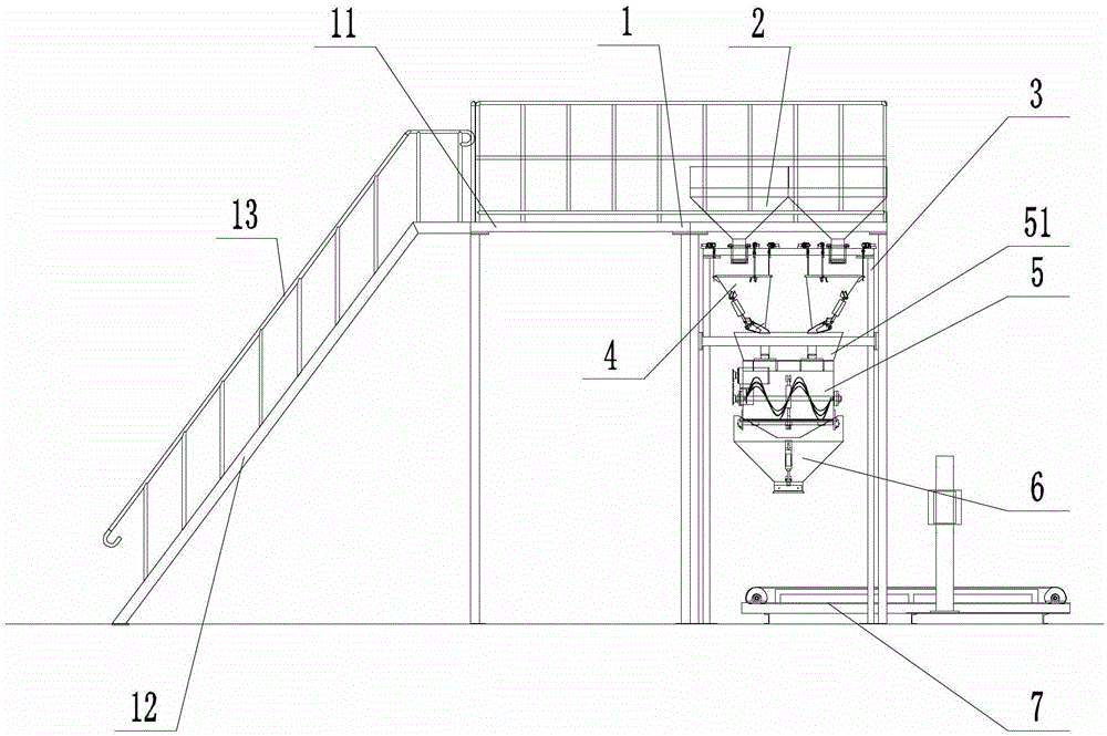
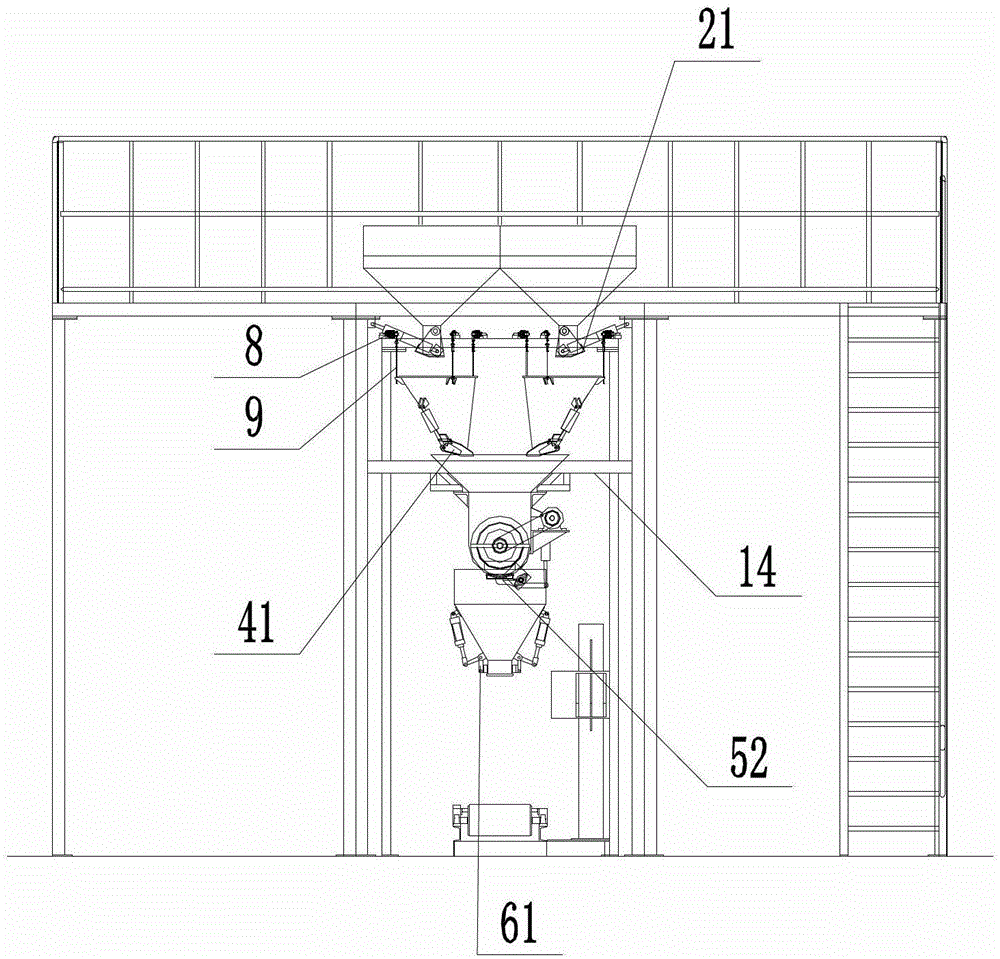
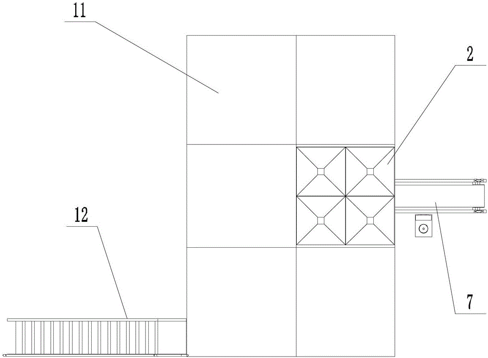
[0017] Examples of the present invention are Figures 1 to 3 As shown, it includes a detachable first frame 1, so when the fertilizer distribution machine needs to be transported, only the first frame 1 needs to be disassembled, and the whole fertilizer distribution machine can be divided into multiple parts that are easy to carry , to avoid the problem that the fertilizer dispensing machine needs to be transported as a whole in the past. After the components of the fertilizer distributing machine are delivered to the destination, the components of the first frame 1 can be connected to each other through bolts, so that the first frame 1 can be reassembled and used; The top of the first frame 1 is provided with a platform 11 for the user to stand and observe the working state of the fertilizer dispenser or to place fertilizers, etc., one side of the platform 11 is provided with a staircase 12 extending to the bottom of the first frame 1, the platform 11 and the stairs 12 are pr...


PUM


Abstract

The invention provides a fertilizer distributing machine comprising a first rack provided with storage bins, wherein metering devices are arranged below the storage bins, a mixing device is arranged below the metering devices, discharge ports of the storage bins correspond to charge ports of the metering devices, and the discharge ports of the storage bins are provided with openable first valves; the metering devices are connected with weight sensors, discharge ports of the metering devices correspond to a charge port of the mixing device, and the discharge ports of the metering devices are provided with openable second valves; a discharge port of the mixing device is provided with a third valve. A second rack separated from the first rack is arranged below the first rack, and the weight sensors are arranged on the second rack. The metering devices are connected with the weight sensors through suspension members, so that the metering devices are in a suspended state. The fertilizer distributing machine not only can reduce failure rate to guarantee a stable operation, but also further improves precision of fertilizer distribution, thereby bringing convenience for users.

Description

technical field [0001] The invention relates to a fertilizer distributing machine, in particular to a fertilizer distributing machine for mixing solid granular fertilizers. Background technique [0002] In order to make the crops grow better, it is often necessary to fertilize them, and because the types of crops and their growth environments are different, the requirements for fertilizers are also different, so there is a fertilizer machine; the commonly used fertilizer The machine is divided into small-scale fertilizer distribution machine and large-scale fertilizer distribution machine. The existing small-scale fertilizer distribution machine transports different fertilizers to different storage bins by the lifting mechanism and transportation device, and then the storage bin passes the quantitative fertilizer through the feeder Discharging, the collecting device collects the discharged fertilizer, transports it to the mixing device for stirring, and finally discharges th...

Claims


Application Information

Patent Timeline
Patent Type & Authority Patents(China)
IPC IPC(8): B01F7/02B01F15/04
Inventor 胡沈阳肖立立
Owner 和原生态控股股份有限公司
Why Eureka
Try Eureka