Foundry waste sand regeneration and shock absorption device

A technology of casting waste sand and shock absorption device, which is applied to casting molding equipment, manufacturing tools, machinery for cleaning/processing of casting materials, etc. Vibration, cheap effect

Active Publication Date: 2013-10-16
CHONGQING CHANGJIANG RIVER MOLDING MATERIAL GRP
View PDF4 Cites 1 Cited by
  • Summary
  • Abstract
  • Description
  • Claims
  • Application Information

AI Technical Summary

Problems solved by technology

[0003] The main technical problem to be solved by the present invention is that the existing vibrating regenerating machine has large noise and unstable movement when vibrating

Method used


Image

  • Foundry waste sand regeneration and shock absorption device

Examples


Embodiment 1

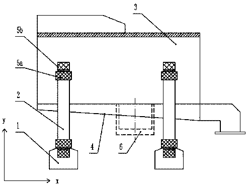
[0014] Such as figure 1 Shown: Foundry waste sand regeneration shock absorption device, including base 1, base 1 is provided with a plurality of support columns 2, support columns 2 are connected to filter screen 3, and below the filter screen 3 is also provided with a conveying plate arranged obliquely 4. The output end of the conveying plate 4 is connected to the hoarding tank of foundry waste sand; the support column 2 is overlapped with a damping spring 5a along the X-axis direction, a damping spring 5b along the Y-axis direction, and a filter screen The bottom of 3 is provided with a vibration source in the Z-axis direction, the vibration source is the eccentric wheel 6, and the eccentric wheel 6 is connected with the motor.

[0015] In this embodiment, the vibration source on the Z-axis direction is turned on to cause the filter screen 3 to vibrate two-dimensionally. Since the support column 2 is connected to the filter screen 3 and the support column 2 is overlapped wit...

Embodiment 2

[0018] Foundry waste sand regeneration and shock absorbing device includes a base 1, a plurality of support columns 2 are arranged on the base 1, the support columns 2 are connected to a filter screen 3, and a conveying plate 4 arranged obliquely is arranged below the filter screen 3 to transport The output end of the plate 4 is connected to the hoarding tank of foundry waste sand; both ends of the support column 2 are overlapped with a damping spring 5a along the X-axis direction, a damping spring 5b along the Y-axis direction, and a filter screen The bottom of 3 is provided with a vibration source in the Z-axis direction, the vibration source is the eccentric wheel 6, and the eccentric wheel 6 is connected with the motor.

[0019] In this embodiment, the vibration source on the Z-axis direction is turned on to cause the filter screen 3 to vibrate two-dimensionally. Since the support column 2 is connected to the filter screen 3 and the support column 2 is overlapped with a dam...


PUM


Abstract

The invention belongs to the field of shock absorption devices and specifically relates to a foundry waste sand regeneration and shock absorption device. The foundry waste sand regeneration and shock absorption device disclosed by the invention comprises a base, wherein a plurality of support columns are arranged on the base, the support columns are connected with a filter screen, shock absorption springs along the directions of an X axis and a Y axis are overlapped on the support columns, and a vibration source in the direction of a Z axis is arranged at the bottom of the filter screen. The vibration source in the direction of the Z axis is opened to enable the filter screen to produce two-dimensional vibration; as the support columns are connected with the filter screen, and the shock absorption springs along the directions of the X axis and the Y axis are overlapped on the support columns, the two-dimensional vibration is promoted to become three-dimensional vibration; and simultaneously, as the shock caused by a pure hard mechanical structure is too severe, the noise is great, the operation of the device is non-smooth and the service life of the whole device is reduced by long-term usage, the shock absorption springs along the directions of the X axis and the Y axis are arranged on the support columns, and then the shock absorption principle of the shock absorption springs is utilized to reduce the vibration in the directions of the X axis and the Y axis, thus the noise is reduced, the operation is smooth, and the service life of the whole device is prolonged.

Description

technical field [0001] The invention belongs to the field of damping devices, in particular to a regeneration damping device for foundry waste sand. Background technique [0002] At present, in foundry machinery, domestic and foreign waste foundry waste sand recycling equipment is mostly used for ordinary vibration type foundry waste sand recycling equipment for dry regeneration. The main working principle of this kind of vibrating foundry waste sand regeneration equipment is to throw up blocky foundry waste sand by vibration force, make the blocky foundry waste sand collide with each other, and rub off the "inert film" on the surface of the waste foundry waste sand. For example, the high-level spiral vibration regenerators currently used in the world work on this principle. However, this type of equipment is noisy and unstable when vibrating. Contents of the invention [0003] The technical problem mainly solved by the invention is that the existing vibrating regenerato...

Claims


Application Information

Patent Timeline
Patent Type & Authority Applications(China)
IPC IPC(8): B22C5/04
Inventor 熊鹰
Owner CHONGQING CHANGJIANG RIVER MOLDING MATERIAL GRP
Why Eureka
Try Eureka