Blade tenon tooth milling clamp

A fixture and tenon milling technology, which is applied in the field of blade milling tenon tooth fixtures, can solve the problems of high dimensional accuracy, large tenon and tenon teeth of blade tooth shape, and difficulties

Active Publication Date: 2013-10-16
四川省自贡市海川实业有限公司
View PDF6 Cites 26 Cited by
  • Summary
  • Abstract
  • Description
  • Claims
  • Application Information

AI Technical Summary

Problems solved by technology

[0002] For blades with vertical tree-shaped roots, the mortise teeth of the blade roots are profiled with arc-shaped teeth and the profile structure is complex (see Image 6 ), the roughness value is very low, the dimensional accuracy is high, and it is a multi-size, multi-parameter surface. It is very difficult. The length of blade tooth section is 120mm on one side. It is finished by forming knife, and its cutting edge is cut at the same time in the range of 120mm. It has a large cutting resistance and is easy to generate vibration, causing ripples and dimensional distortion on the processed surface. , so that the quality of the blades is not good enough, or even scrapped

Method used


Image

  • Blade tenon tooth milling clamp
  • Blade tenon tooth milling clamp
  • Blade tenon tooth milling clamp

Examples


Embodiment Construction

[0022] The present invention will be further described below in conjunction with accompanying drawing.

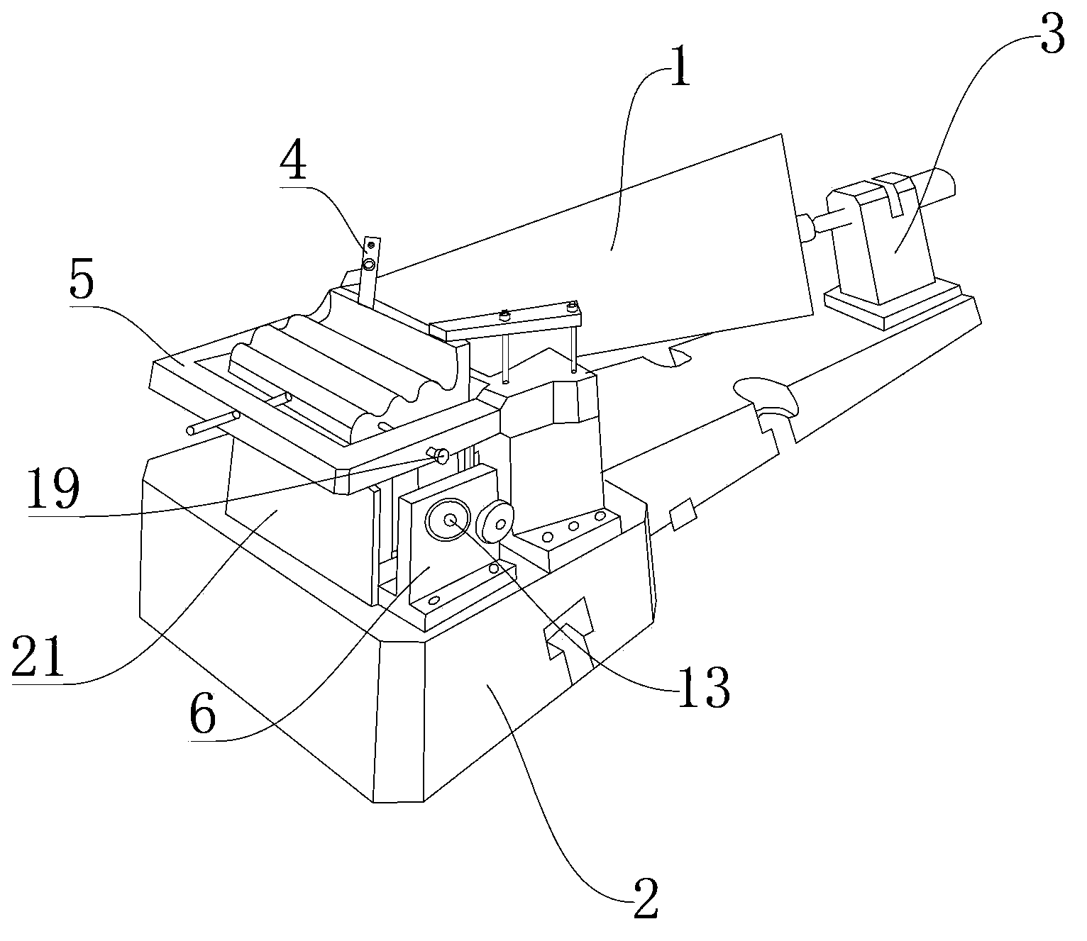
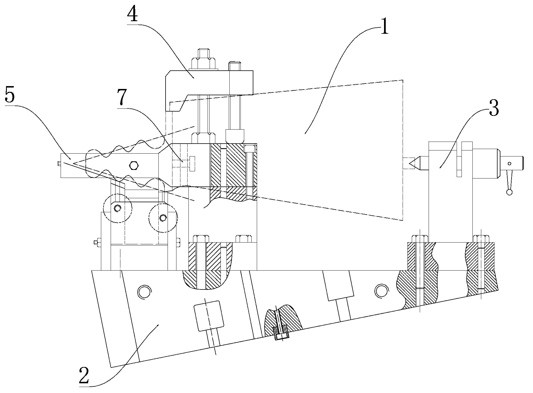
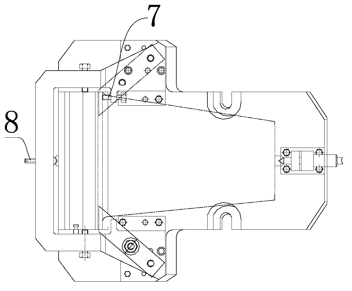
[0023] Such as Figure 1 to Figure 6 A blade milling jig shown is used to clamp the blade 1. The jig is fixed on the machining table of the machine tool for processing blade tenon teeth, and includes a bottom plate 2, which is provided with a blade top clamping device for positioning the blade top. , a blade root clamping device for positioning the blade root 10 is also provided, and the blade root clamping device includes a cantilever bow 5 with a bow tip 8 (the cantilever bow 5 is supported by two iron seats, and the bow part is suspended on In the air), the bottom plate 2 is fixed with an inclined sliding seat 18 whose upper end surface is inclined and located at the lower end of the cantilever bow frame 5. The middle part of the inclined sliding seat 18 includes a positioning block 17 for longitudinally positioning the blade shoulder. The two sides of the positioning bl...


PUM


Abstract

The invention relates to a blade tenon tooth milling clamp which is used for clamping a blade. The blade tenon tooth milling clamp is fixed on the processing platform of a blade tenon tooth processing machine tool and comprises a baseplate arranged on the processing platform; a blade top clamping device for positioning a blade top and a blade root clamping device for positioning a blade root are arranged on the baseplate; an oblique slide seat arranged at the lower end of a cantilever bow rack is fixed on the baseplate, and the upper end surface of the oblique slide seat is inclined; a positioning block for lengthwise positioning a blade shoulder is arranged in the middle of the oblique slide seat; a first oblique slide block and a second oblique slide block are arranged on two sides of the positioning block respectively and are used for positioning tenon teeth; the first oblique slide block and the second oblique slide block can slide and be fixed along the upper end surface of the oblique slide seat. With the structure, the blade tenon tooth milling clamp has the advantages that the slide blocks on the baseplate can be moved and fixed along the oblique slide seat, so that the lower parts of the tenon teeth are prevented from suspending in the air but are support tightly, and the tenon teeth are stressed uniformly and stably; fixed-pitch positioning blocks are arranged in the longitudinal direction at two ends of the blade and the blade is finely adjusted and propped by two centres and locked by bolts so as to meet the requirements for dimension consistency and position symmetry when the blade is overturned and processed.

Description

technical field [0001] The invention belongs to the field of blade clamps, and in particular relates to a blade milling tenon tooth clamp. Background technique [0002] For blades with vertical tree-shaped roots, the mortise teeth of the blade roots are profiled with arc-shaped teeth and the profile structure is complex (see Image 6 ), the roughness value is very low, the dimensional accuracy is high, and it is a multi-size, multi-parameter surface. It is very difficult. The length of blade tooth section is 120mm on one side. It is finished by forming knife, and its cutting edge is cut at the same time in the range of 120mm. It has a large cutting resistance and is easy to generate vibration, causing ripples and dimensional distortion on the processed surface. , so that the quality of the blades is not good enough, or even scrapped. Contents of the invention [0003] The purpose of the present invention is to provide a blade milling tenon with uniform and stable force, g...

Claims


Application Information

Patent Timeline
Patent Type & Authority Applications(China)
IPC IPC(8): B23Q3/06
Inventor 刘建文
Owner 四川省自贡市海川实业有限公司
Why Eureka
Try Eureka