Unlock instant, AI-driven research and patent intelligence for your innovation.

Internal mixer

An internal mixer and internal mixing technology, applied in the mechanical field, can solve the problems of easy wear and tear of the internal mixing chamber, reduce the service life of the internal mixing shaft, and easily damage the internal structure of the contact surface, and achieve the diversification of the cooling system and the expansion of the scope of use. Effect

Inactive Publication Date: 2013-10-16
ZHEJIANG LIDA RUBBER & PLASTIC MACHINERY
View PDF4 Cites 6 Cited by
  • Summary
  • Abstract
  • Description
  • Claims
  • Application Information

AI Technical Summary

Problems solved by technology

However, the existing internal mixer includes a mixing chamber, a mixing shaft, an upper top bolt and a lower top bolt, the upper top bolt and the lower top bolt are respectively movably connected with the banbury shaft, and the banbury shaft is located in the banbury chamber. During the working process of the machine, the mixing chamber, the mixing shaft and the lower top bolt are all in contact with the feed liquid. Due to the high temperature of the feed liquid, the contact surface between the mixing chamber, the banbury shaft and the lower top bolt and the feed liquid Changes in stress can easily damage the internal structure of the contact surface, causing the contact surface of the mixing chamber, the bottom bolt of the mixer shaft and the material liquid to be easily worn, which greatly reduces the service life of the mixer shaft and makes the overall mixer Unreasonable structural layout

Method used


Image

  • Internal mixer
  • Internal mixer
  • Internal mixer

Examples


Embodiment Construction

[0023] The following will clearly and completely describe the technical solutions in the embodiments of the present invention with reference to the accompanying drawings in the embodiments of the present invention. Obviously, the described embodiments are only some, not all, embodiments of the present invention. Based on the embodiments of the present invention, all other embodiments obtained by persons of ordinary skill in the art without creative efforts fall within the protection scope of the present invention.

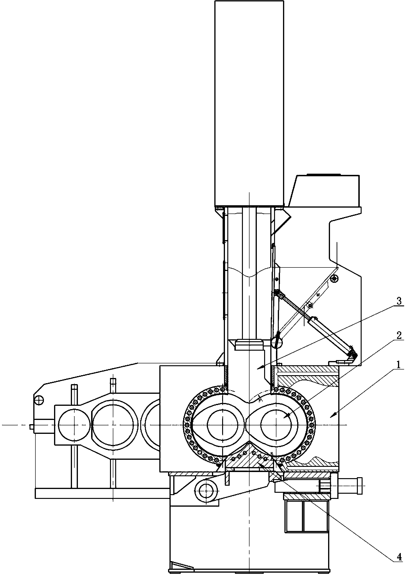
[0024] Such as figure 1 — Figure 6 As shown, the present invention discloses a banbury mixer, comprising a banburying chamber 1, a banburying shaft 2, an upper top bolt 3 and a lower top bolt 4, the upper top bolt 3 and the lower top bolt 4 are movably connected with the banburying chamber 1 , the banburying shaft 2 is located in the banburying chamber 1, and the two ends of the banburying shaft 2 pass through the banburying chamber 1, and the connection between ...


PUM


Abstract

The invention relates to the field of machinery, in particular to an internal mixer. The invention adopts the technical scheme as follows: the internal mixer comprises a mixer chamber, a mixer shaft and a lower ram, wherein a first coolant gallery is arranged on one side wall of the mixer chamber, a second coolant gallery is arranged on one side wall of the lower ram, a third coolant gallery is arranged on the mixer shaft, and the first coolant gallery, the second coolant gallery and the third coolant gallery are connected with a cooling system respectively. The internal mixer has the advantages that the temperature of the contact surfaces of the mixer chamber, the mixer shaft and the lower ram with feed liquid are reduced greatly, so that the internal stress of the contact surfaces of the mixer chamber, the mixer shaft and the lower ram with the feed liquid is not easy to change, the internal structures of the contact surfaces are protected, the contact surfaces of the mixer chamber, the mixer shaft and the lower ram with the feed liquid are not easy to wear, the service life of the mixer shaft is prolonged on the whole, and the structure layout is more reasonable.

Description

technical field [0001] The invention relates to the field of machinery, in particular to an internal mixer. Background technique [0002] The internal mixer is used for rubber, plastic and mastication and mixing of various rubber materials and plastics. It melts the PVC mixture in a very short time and promotes gelation. Colorants and foaming agents are added and mixed here. However, the existing internal mixer includes a mixing chamber, a mixing shaft, an upper top bolt and a lower top bolt, the upper top bolt and the lower top bolt are respectively movably connected with the banbury shaft, and the banbury shaft is located in the banbury chamber. During the working process of the machine, the mixing chamber, the mixing shaft and the lower top bolt are all in contact with the feed liquid. Due to the high temperature of the feed liquid, the contact surface between the mixing chamber, the banbury shaft and the lower top bolt and the feed liquid Changes in stress can easily da...

Claims


Application Information

Patent Timeline
Patent Type & Authority Applications(China)
IPC IPC(8): B29B7/82
CPCB29B7/183B29B7/24B29B7/7495B29B7/826
Inventor 董志平董志坚
Owner ZHEJIANG LIDA RUBBER & PLASTIC MACHINERY