Carding roller bearing

A technology of carding rollers and bearings, applied in the directions of bearing components, shafts and bearings, mechanical equipment, etc., can solve the problems of short service life of bearings, and achieve the effect of prolonging service life, improving quality and prolonging life.

Inactive Publication Date: 2013-10-16
无锡市宏飞工贸有限公司
View PDF7 Cites 0 Cited by
  • Summary
  • Abstract
  • Description
  • Claims
  • Application Information

AI Technical Summary

Problems solved by technology

[0003] In view of the lack of oiling structure in the above-mentioned existing production technology, which leads to the short service life of the bearing and other shortcomings, the applicant provides a kind of carding roller bearing with a reasonable structure, thereby adding oiling structures at both ends of the mandrel, so that it can operate at high speed. During operation, the grease can be replenished into the groove in time, reducing the friction and wear of the rolling elements in the bearing, the outer ring, and the mandrel, prolonging the service life, improving the quality of spinning, and reducing costs

Method used


Image

  • Carding roller bearing
  • Carding roller bearing

Examples


Embodiment Construction

[0017] The specific implementation manner of the present invention will be described below in conjunction with the accompanying drawings.

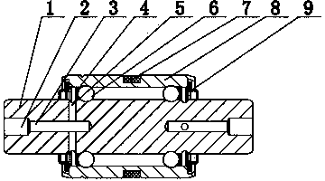
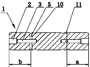
[0018] Such as figure 1 and figure 2 As shown, the carding roller bearing of this embodiment includes rolling elements 6 installed between the outer ring 8 and the mandrel 1, the cage 4 isolating the rolling elements 6, and the dust-proof ring 9 is installed in the dust-proof groove of the outer ring 8. The positioning ring 7 is installed on the outer circumferential surface of the outer ring 8; the two ends of the mandrel 1 are respectively provided with oiling structures, and the two ends of the mandrel 1 are respectively opened with axial oiling holes 3, which are located at the outer ends of the axial oiling holes 3 A counterbore 2 is extended, and an oil plug head (not shown in the figure) is installed in the counterbore 2; a mandrel channel 10 is arranged on the mandrel 1, and the outer circle of the mandrel 1 located at both ends ...


PUM


Abstract

The invention relates to a carding roller bearing, which comprises an outer ring and a core shaft, wherein rolling bodies are mounted between the outer ring and the core shaft; holding racks are used for isolating the rolling bodies; scraper seals are mounted in dustproof grooves of the outer ring; a positioning ring is mounted on the outer circumferential surface of the outer ring; oiling structures are arranged at the two ends of the core shaft respectively; axial direction oil holes are formed in the two ends of the core shaft respectively; counter bores are positioned in the outer ends of the axial direction oil holes in an extending manner; oil plug heads are mounted in the counter bores; a core shaft gutter channel is arranged on the core shaft; outer circle grooves are formed in the outer circle of the core shaft and positioned at the two ends of the core shaft gutter channel; radial direction through-holes are formed along the positions of the outer circle grooves; the radial direction through-holes penetrate the axial direction oil holes. The carding roller bearing is compact and reasonable in structure. The oiling structures are arranged on the core shaft, so that lubrication in the process of use of the bearing can be realized conveniently, and the service life of the bearing is prolonged.

Description

technical field [0001] The invention relates to the technical field of textile accessories, in particular to a carding roller bearing used on a rotor spinning machine. Background technique [0002] In the prior art, the carding roller bearing used on the rotor spinning machine mainly includes an outer ring, a mandrel, a cage, rolling elements (rollers or balls), a dustproof ring, and a positioning ring. The rolling elements (rollers or balls) are installed between the outer ring and the mandrel, and the cage is used for positioning. The cage evenly isolates the rolling elements and keeps the rolling elements moving correctly. The dust-proof ring is placed in the dust-proof groove of the outer ring for positioning. The circle acts as a positioning function. Its structure is simple and reasonable, but the bearing of this structure is not equipped with a reasonable oiling structure, so that the bearing will be used for a period of time under the condition of continuous high-sp...

Claims


Application Information

Patent Timeline
Patent Type & Authority Applications(China)
IPC IPC(8): F16C33/66
Inventor 吉云飞陈建
Owner 无锡市宏飞工贸有限公司
Why Eureka
Try Eureka