Laser marking device for circular sawing machine

A technology of laser marking and circular sawing machine, which is applied in the direction of sawing machine accessories, sawing machine devices, metal sawing equipment, etc., and can solve the problems of users' dimensional cognition confusion, limited adjustment, slow adjustment speed, etc.

Inactive Publication Date: 2013-10-23
REXON IND CORP LTD
View PDF7 Cites 7 Cited by
  • Summary
  • Abstract
  • Description
  • Claims
  • Application Information

AI Technical Summary

Problems solved by technology

In the known technology, the lenses that generate the plane light beams are directly installed in the laser module for the adjustment of the laser marking line. The user must turn the screws 35S, 38S, and 34 one by one through tools to perform the adjustment. In addition to the problem that the adjustment speed is too slow when adjusting the structural design of the device, the adjustment of each dimension is limited by the design of the laser module itself, which sometimes affects each other, causing confusion for the user's cognition of the dimension. At the same time, the user's skills It is also related to the effect of adjustment, which is quite troublesome and inconvenient for users

Method used


Image

  • Laser marking device for circular sawing machine
  • Laser marking device for circular sawing machine
  • Laser marking device for circular sawing machine

Examples


Embodiment Construction

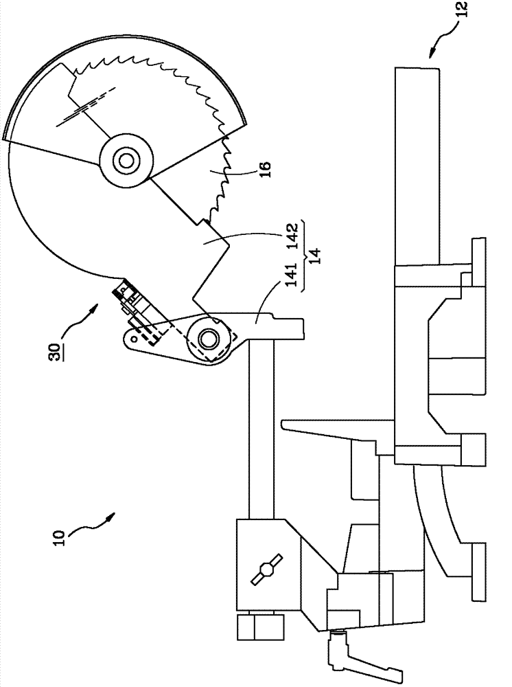
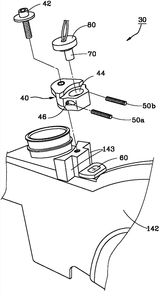
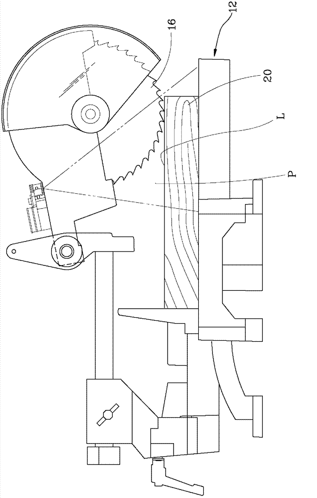
[0029] The laser marking device of the present invention includes an adjustment seat, a lens, and a laser generator. The adjustment seat is pivoted on a saw arm of the circular saw machine by a rotating shaft and has a through hole; the lens is arranged on the saw arm corresponding to the adjustment seat; the laser generator is arranged on the knob and accommodated in the adjustment seat In the through hole, it is used to generate a laser beam. As a result, when the laser beam passes through the lens, it will diffuse to form a plane beam, which is projected on a workpiece to form a laser marking line. The plane beam can be moved in a swing by the pivoting of the adjustment seat relative to the saw arm, The plane light beam is quickly switched between a predetermined first plane position and a predetermined second plane position substantially parallel to the planes on both sides of the saw blade, so that the purpose of quickly adjusting the laser marking line can be achieved. ...


PUM


Abstract

The invention relates to a laser marking device for a circular sawing machine. The laser marking device comprises an adjusting seat, a lens and a laser generator, wherein the adjusting seat is pivoted to a saw arm, the lens is arranged on the saw arm, and the laser generator is arranged on the adjusting seat. When a laser beam generated by the laser generator passes the lens, the laser beam can be diffused to form a planar light beam and can be projected onto a workpiece to form a laser marking line, and the planar light beam can be rapidly switched and moved between a preset first plane position and a preset second plane position which are approximately parallelly aligned to planes on two sides of a saw blade by rapidly moving the adjusting seat, so that the laser marking line can be rapidly adjusted.

Description

technical field [0001] The invention relates to a circular saw machine, in particular to a laser marking device for a circular saw machine. Background technique [0002] When the user operates the circular saw to cut the workpiece, he usually first draws a cutting line on the surface of the workpiece, then presses down the circular saw blade to touch the workpiece and visually judges the corresponding cutting line of the circular saw blade, and then follows the cutting line after confirmation. The cutting line cuts the workpiece, but in the process of aligning the circular saw blade to the cutting line, because of the limitation of the shape of the circular saw blade, it can only be partially aligned to the cutting line, so errors are prone to occur, which will cause the workpiece to be damaged after cutting. The size is too large or too small, so the existing circular saw machine is equipped with a set of laser marking device, the laser beam generated by the laser marking d...

Claims


Application Information

Patent Timeline
Patent Type & Authority Applications(China)
IPC IPC(8): B23D59/00B23Q17/22B23Q17/24B23D47/00
Inventor 陈荣火
Owner REXON IND CORP LTD
Why Eureka
Try Eureka