
Redundant drive symmetric three degree-of-freedom mobile parallel mechanism

A degree of freedom, symmetrical technology, applied in the field of robotics, can solve the problem of redundant drive three-degree-of-freedom mobile parallel mechanism report and other issues

Inactive Publication Date: 2013-10-23
YANSHAN UNIV
View PDF8 Cites 9 Cited by
  • Summary
  • Abstract
  • Description
  • Claims
  • Application Information

AI Technical Summary

Problems solved by technology

Up to now, there have been many reports on three-degree-of-freedom mobile parallel mechanisms, but they are all non-redundant drive mechanisms, that is, the number of input motion pairs is equal to the number of degrees of freedom, and there is no report on redundant-driven three-degree-of-freedom mobile parallel mechanisms

Method used


Image

  • Redundant drive symmetric three degree-of-freedom mobile parallel mechanism
  • Redundant drive symmetric three degree-of-freedom mobile parallel mechanism

Examples


Embodiment 1

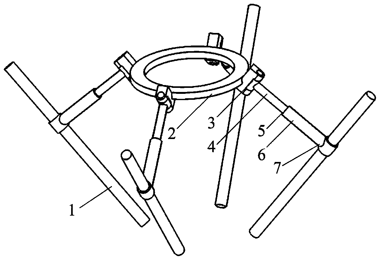
[0012] exist figure 1 In the schematic diagram of the redundant drive symmetrical three-degree-of-freedom mobile parallel mechanism shown, four branch chains with the same structure connect the moving platform 2 and the four fixed guide rails 1, and the four fixed guide rails are evenly distributed on the same conical surface. One end of the upper connecting rod 4 is connected with the moving platform through the rotating pair 3, the other end of the upper connecting rod is connected with one end of the lower connecting rod 6 through the moving pair, and the other end of the lower connecting rod is connected with the fixed guide rail through the cylindrical pair 7 , the moving part of the cylindrical pair is the input kinematic pair, the axis of the cylindrical pair coincides with the axial direction of the fixed guide rail, and the four rotating pairs on the four branch chains are evenly distributed on the moving platform. The axis of the cylinder pair is parallel, and the ax...

Embodiment 2

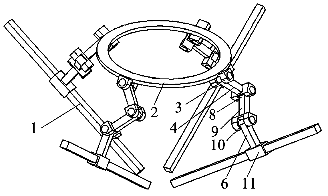
[0014] exist figure 2 In the schematic diagram of the redundant drive symmetrical three-degree-of-freedom mobile parallel mechanism shown, four branch chains with the same structure connect the moving platform 2 and the four fixed guide rails 1, and the four fixed guide rails are evenly distributed on the same conical surface. One end of the upper connecting rod 4 is connected with the moving platform through the rotating pair 3, the other end of the upper connecting rod is connected with one end of the middle connecting rod 9 through the rotating pair 8, and the other end of the middle connecting rod is connected with the lower connecting rod through the rotating pair 10. One end of the rod 6 is connected, and the other end of the lower connecting rod is connected with the fixed guide rail through the moving pair 11. The moving pair is an input kinematic pair, and its axis coincides with the axial direction of the fixed guide rail. The axes of the moving pairs are parallel, ...


PUM


Abstract

The invention discloses a redundant drive symmetric three degree-of-freedom mobile parallel mechanism, which mainly comprises four fixed guide rails, a moving platform and four branched chains with the identical structure and for connecting the moving platform and the fixed guide rails, wherein the four fixed guide rails are uniformly distributed on the same conical surface, one ends of upper connecting rods of the branched chains are connected with the moving platform through revolute pairs, the other ends of the upper connecting rods are connected with one ends of lower connecting rods through sliding pairs, the other ends of the lower connecting rods are connected with the fixed guide rails through cylindrical pairs, the mobile parts of the cylindrical pairs are input kinematic pairs, the axial lines of the cylindrical pairs coincide with the axial directions of the fixed guide rails, the four revolute pairs on the four branched chains are uniformly distributed on the moving platform, the axial lines of the revolute pairs are parallel to the axial lines of the cylindrical pairs, and the axial lines of the sliding pairs are perpendicular to the axial lines of the cylindrical pairs. The mechanism has the advantages of large bearing capacity and excellent isotropy.

Description

technical field [0001] The invention belongs to the field of robots, in particular to a parallel mechanism. Background technique [0002] The parallel mechanism with few degrees of freedom has the advantages of simple structure, low manufacturing cost, and easy control. In recent years, it has become one of the research hotspots in the field of robotics and mechanisms. The three-degree-of-freedom mobile parallel mechanism is a kind of less-freedom parallel mechanism that is widely used in actual production, among which the DELTA robot is a mobile parallel robot that is very successful in industrial production. Up to now, there have been many reports on three-degree-of-freedom mobile parallel mechanisms, but they are all non-redundant drive mechanisms, that is, the number of input kinematic pairs is equal to the number of degrees of freedom, and there is no report on redundant-driven three-degree-of-freedom mobile parallel mechanisms. Contents of the invention [0003] The...

Claims


Application Information

Patent Timeline
IPC IPC(8): B25J9/00
Inventor 许允斗赵永生周鑫姚建涛
Owner YANSHAN UNIV
Learn More