Lighting device
A technology for lighting devices and radiators, applied in lighting devices, lighting and heating equipment, light sources, etc., can solve problems such as low efficiency
- Summary
- Abstract
- Description
- Claims
- Application Information
AI Technical Summary
Problems solved by technology
Method used
Image
Examples
Embodiment approach 1
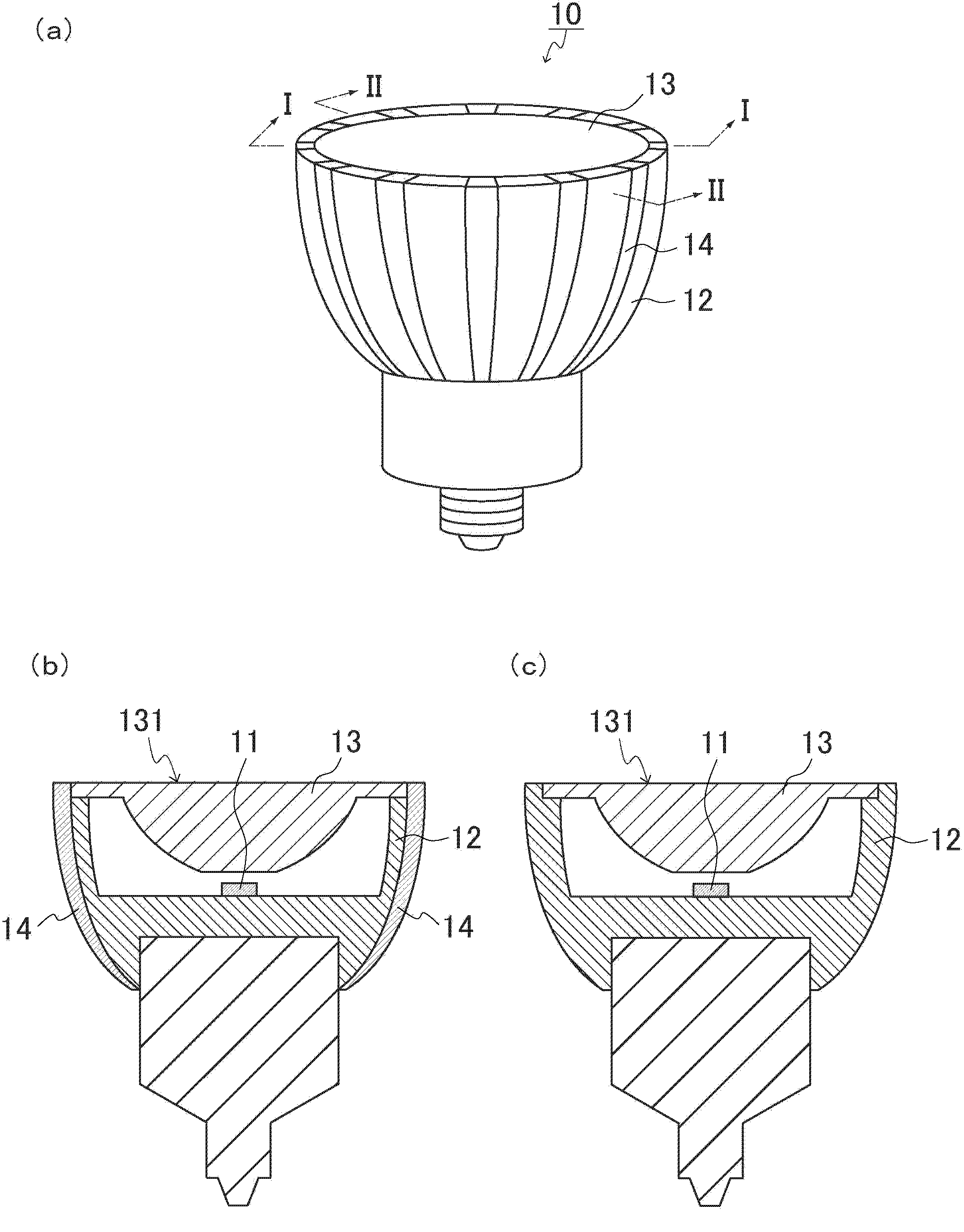
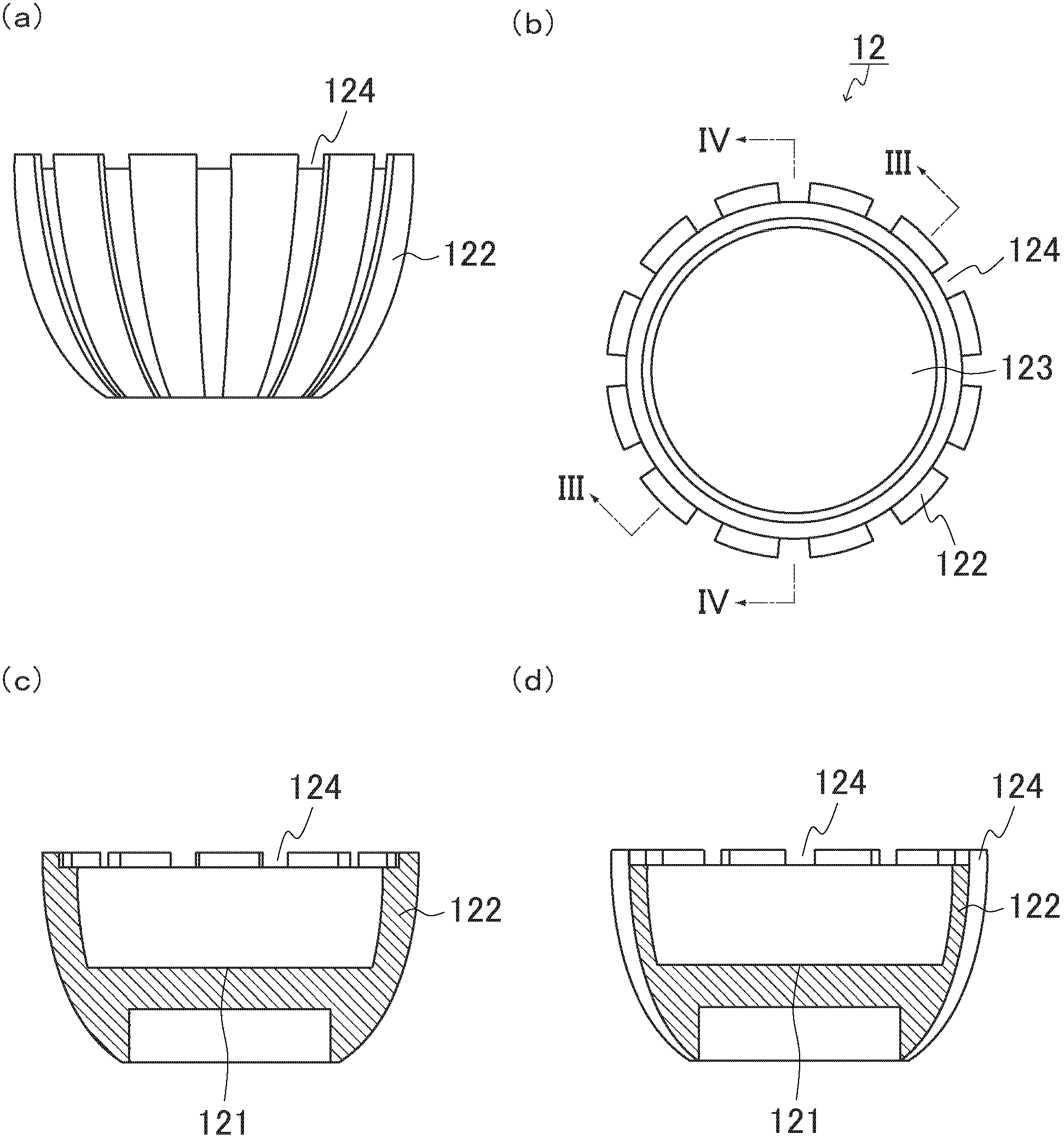
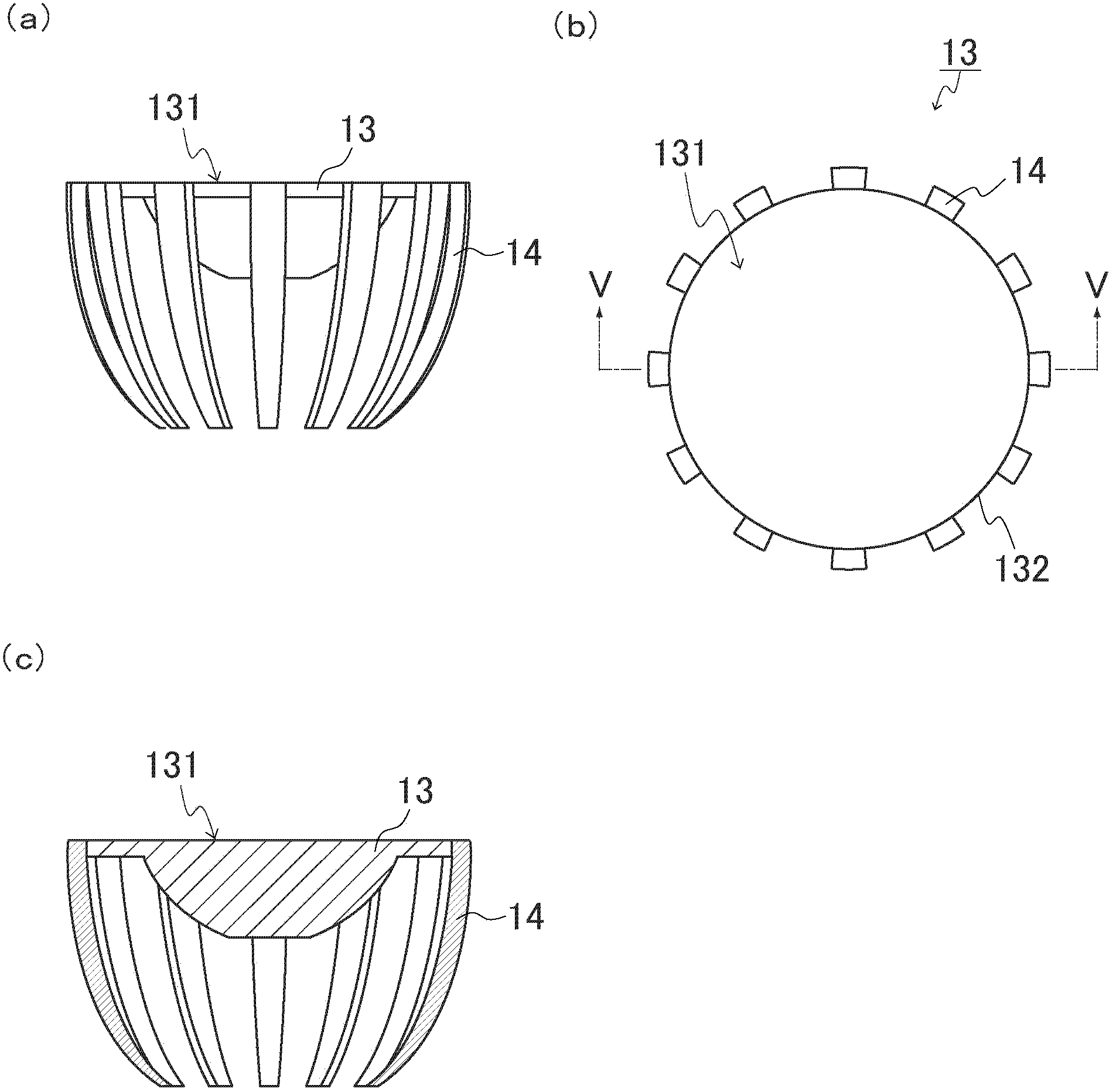
[0024] The lighting device of the present embodiment is an example of a bulb-type LED lamp used in place of a halogen bulb. figure 1 The structure of the bulb-type LED lamp used for replacing a halogen bulb in this embodiment is shown. figure 1 (a) is a perspective view showing the structure of the bulb-type LED lamp, figure 1 (b) is figure 1 The cross-sectional view of the above-mentioned light bulb type LED lamp shown in (a) to I-I direction observation, figure 1 (c) is figure 1 (a) The sectional drawing seen from II-II direction of the said light bulb type LED lamp shown. figure 2 The structure of the heat sink in the above-mentioned bulb-type LED lamp is shown. figure 2 (a) is a side view showing the structure of the radiator, figure 2 (b) is a top view showing the structure of the radiator, figure 2 (c) is figure 2 The cross-sectional view of the above-mentioned radiator shown in (b) viewed from the III-III direction, figure 2 (d) is figure 2 A cross-secti...
Embodiment approach 2
[0035] The lighting device of the present embodiment is an example of a bulb-type LED lamp used in place of a halogen bulb. Figure 4 The structure of the bulb-type LED lamp used for replacing a halogen bulb in this embodiment is shown. Figure 4 (a) is a side view showing the structure of the heat sink in the bulb-type LED lamp, Figure 4 (b) is a plan view showing the structure of the heat sink in the bulb-type LED lamp, Figure 4 (c) is a perspective view showing the structure of the bulb-type LED lamp, Figure 4 (d) is Figure 4 (c) The cross-sectional view seen from VI-VI direction of the said light bulb type LED lamp shown.
[0036] Such as Figure 4 As shown, the bulb-type LED lamp 20 of this embodiment includes a heat sink 22 instead of the heat sink 12, and has the same Figure 1~3 The bulb-type LED lamp 10 shown has the same structure.
[0037] The heat sink 22 has the same structure as the heat sink 12 except that a slit 224 is provided instead of the groove p...
Embodiment approach 3
[0042] The lighting device of the present embodiment is an example of a bulb-type LED lamp used in place of a halogen bulb. Figure 5 The structure of the bulb-type LED lamp used for replacing a halogen bulb in this embodiment is shown. Figure 5 (a) a perspective view showing the structure of the heat sink in the above bulb-type LED lamp, Figure 5 (b) is a perspective view showing the structure of the lens and the light guide in the bulb-type LED lamp, Figure 5 (c) is a perspective view showing the structure of the bulb-type LED lamp, Figure 5 (d) is Figure 5 (c) The cross-sectional view seen from the VII-VII direction of the said light bulb type LED lamp shown.
[0043] Such as Figure 5 As shown, the bulb-type LED lamp 30 of this embodiment includes an LED element 11 , a heat sink 32 , a lens 13 , and a light guide 34 as main components. The heat sink 32 has a bottomed cylindrical shape having a bottom 321 and a side wall 322 , and has an upper opening (opening 323...
PUM
 Abstract
Description
Claims
Application Information
 - R&D
- Intellectual Property
- Life Sciences
- Materials
- Tech Scout
- Unparalleled Data Quality
- Higher Quality Content
- 60% Fewer Hallucinations
Browse by: Latest US Patents, China's latest patents, Technical Efficacy Thesaurus, Application Domain, Technology Topic, Popular Technical Reports.
© 2025 PatSnap. All rights reserved.Legal|Privacy policy|Modern Slavery Act Transparency Statement|Sitemap|About US| Contact US: help@patsnap.com


