Circuit breaker motion mechanism

A technology of action mechanism and circuit breaker, applied in the direction of protection switch operation/release mechanism, etc., which can solve the problems of long inherent time of action mechanism and difficulty in absorbing and extinguishing arcs.

Active Publication Date: 2013-10-23
SHANGHAI LIANGXIN ELECTRICAL
View PDF7 Cites 0 Cited by
  • Summary
  • Abstract
  • Description
  • Claims
  • Application Information

AI Technical Summary

Problems solved by technology

[0004] The operating mechanism and arc extinguishing device of the circuit breaker have a decisive influence on its breaking capacity. For example, due to the limitation of the mechanism device and arc extinguishing device, the breaking capacity of the conventional C45 series circuit breaker is 63A / 230V. The inherent time of mechanism movement is longer
Tests have proved that the inherent time of conventional C45 products is generally 6-8ms, which is very difficult to absorb and extinguish the arc.

Method used


Image

  • Circuit breaker motion mechanism
  • Circuit breaker motion mechanism

Examples


Embodiment Construction

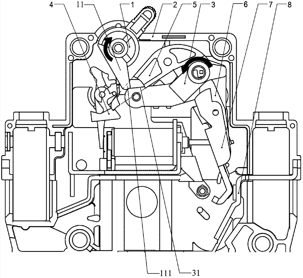
[0016] Such as figure 1 As shown, the operating mechanism of the circuit breaker of the present invention includes the handle 1, the upper link 3 and the movable contact 7 installed in the base 2, but there is no U-shaped link between the handle 1 and the upper link 3, and no other The connecting member, but protrudes a swing arm 11 from the handle. In this preferred embodiment, the swing arm 11 and the handle 1 are integrally formed, and the movable contact 7 is rotatably connected to a bracket 6 .

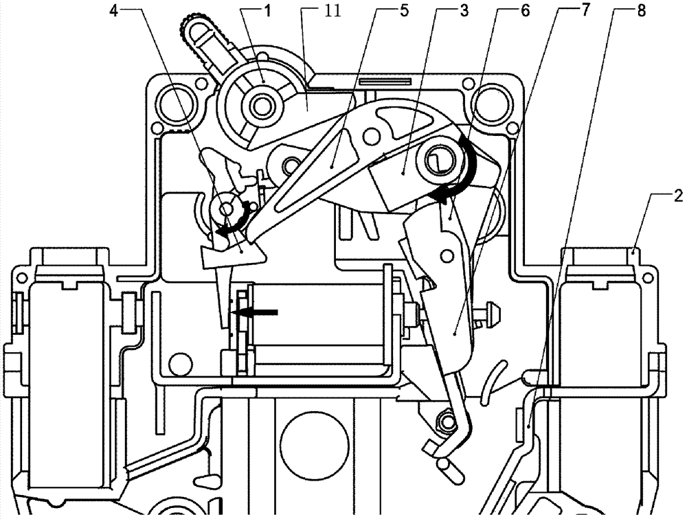
[0017] In the open state, such as figure 2 As shown, the handle 1 including the swing arm 11 is not in contact with the upper link 3 and is completely separated.

[0018] Only when turning the handle to close, such as figure 1 When the handle 1 is turned clockwise, the lower end 111 of the swing arm will come into contact with the upper surface 31 of the upper link and generate sliding friction, thereby pushing the upper link 3 to rotate, and then the link will drive the lock...


PUM


Abstract

The invention discloses a circuit breaker motion mechanism comprising a handle, an upper connecting rod, a moving contact head, a jumping fastener and a locking fastener. When the handle rotates, the upper connecting rod and the moving contact head are driven to rotate, and switch-on and switch-off are realized; when the jumping fastener is separated from the locking fastener, the upper connecting rod and the moving contact head rotate, and therefore the switch-off is realized; no connecting member is arranged between the handle and the upper connecting rod; when the switch-off is realized, the handle and the upper connecting rod respectively rotate in an independent manner; a swing arm protrudes on the handle; when the switch-on is realized by rotating the handle, the lower end of the swing arm contacts with the upper surface o the upper connecting rod and sliding friction is generated, and therefore the upper connecting rod and the moving contact head are enabled to rotate. The circuit breaker motion mechanism is characterized in that the connecting member between the handle and the upper connecting rod is eliminated; when the switch-on is realized, the swinging arm protruding on the handle can contact with the upper connecting rod to drive the upper connecting rod to move; when the switch-off is realized, the handle and the upper connecting rod can rotate respectively and independently without any friction or restriction between the handle and the upper connecting rod, mutual interference is prevented, and therefore the breaking speed of a circuit breaker is improved.

Description

technical field [0001] The invention relates to an action mechanism for realizing the opening and closing movement of a circuit breaker, which belongs to the field of low-voltage electrical appliances. Background technique [0002] At present, the action mechanism of a common small circuit breaker is generally composed of a handle, a U-shaped connecting rod, a transmission rod, a moving contact, a jumper and a lock. When the handle is pulled, the U-shaped connecting rod drives the transmission rod and the moving contact. The head moves to make the moving contact contact or separate from the static contact to realize closing or opening; when the tripping mechanism releases the interlocking jumper and lock, the action mechanism will also act to make the moving contact and the The static contacts are separated to realize opening. [0003] For example, Chinese utility model patent 201020506403.0 discloses a circuit breaker handle connection structure, which includes a handle co...

Claims


Application Information

Patent Timeline
Patent Type & Authority Applications(China)
IPC IPC(8): H01H71/10
Inventor 冯洪宝于贻鹏段辉
Owner SHANGHAI LIANGXIN ELECTRICAL
Why Eureka
Try Eureka