Gas turbine guide flow disk

A gas turbine and deflector technology, applied in the field of turbines, can solve the problems of increasing the burden on the turbine disk, shifting the center of gravity of the structure to the right, and reducing the rupture speed, etc., so as to reduce the centrifugal load, meet the design requirements, and reduce the stress level.

Active Publication Date: 2015-09-09
CHINA AVIATION POWER MACHINE INST
View PDF4 Cites 6 Cited by
  • Summary
  • Abstract
  • Description
  • Claims
  • Application Information

AI Technical Summary

Problems solved by technology

[0004] The snap ring structure used in the prior art interacts with the turbine disk, increasing the burden on the turbine disk; the existence of the snap ring moves the center of gravity of the structure to the right, which easily leads to the displacement of the seal; the existence of the snap ring increases its own Weight, resulting in increased stress level, reduced rupture speed, and shortened fa

Method used


Image

  • Gas turbine guide flow disk
  • Gas turbine guide flow disk
  • Gas turbine guide flow disk

Examples


Embodiment Construction

[0027] The embodiments of the present invention will be described in detail below with reference to the accompanying drawings, but the present invention can be implemented in many different ways defined and covered by the claims.

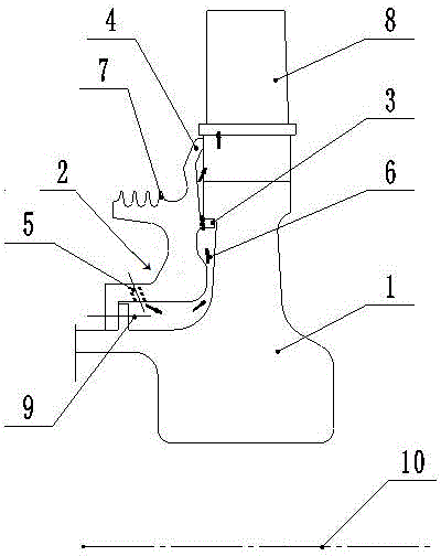
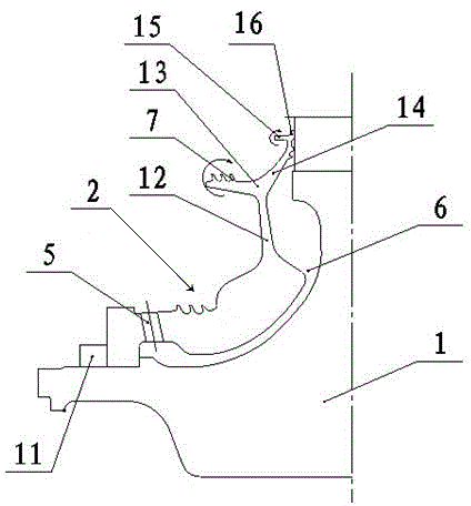
[0028] Such as figure 2 As shown, the present invention provides a gas turbine deflector plate 2, which includes a connecting end, an intermediate section 12 and a sealing end connected in sequence, and the intermediate section 12 connects the connecting end and the sealing end; The position of the middle section is divided into the seal 4 and the tooth end 7 to both sides respectively, and the starting position of the differentiation to both sides is the bifurcation 13;

[0029] The middle section 12 is a flexible thin plate whose thickness gradually decreases from both ends to the middle, so that the part above the middle section 12 is prone to rotate around the center of the bifurcation 13 under the action of centrifugal force;

[0030] The thi...


PUM

PropertyMeasurementUnit
Thicknessaaaaaaaaaa
Thicknessaaaaaaaaaa
Thicknessaaaaaaaaaa

Abstract

The invention provides a gas turbine guide flow disk. Through arranging a flexible thin plate and adjusting a sealing structure, the pressing force of a sealing structure to a turbine disk is realized, so that the sealing structure can automatically bond to the turbine disk under the function of centrifugal force, so as to further guarantee the sealing reliability; the guide flow disk is positioned without the use of a 'snap ring'; besides, the gas turbine guide flow disk can eliminate the technical shortcomings of increased burden of turbine disk, raised stress level, and reduced rotate speed brought by the 'snap ring' in the prior art. The guide flow disk has good axial symmetry, good technique, and high reliability; for the thickness of a part having big radius of the guide flow disk and consisting of a fork, a middle section and a middle wheel plate is relatively thin, the centrifugal load is reduced; therefore, the stress level is decreased, the rupture rotate speed is improved, the fatigue service life is prolonged, weight is lightened, and the burden of the turbine disk is reduced, and demand of a high-performance aero-engine can be satisfied.

Description

technical field [0001] The invention relates to the technical field of turbines, and more specifically, to a gas turbine deflector. Background technique [0002] The main function of the deflector plate is to form a cooling gas passage together with the (gas or high pressure) turbine disk, and to ensure the sealing of the passage during the working process, so as to "guide" the cold air to the mortise (connection) joints and blades. In some cases, it also prevents the turbine blade (tenon) from sliding along the tenon groove. [0003] figure 1 Shown is a gas turbine deflector of prior art design. The guide disc 2 and the turbine disc 1 are connected to each other at the bolt connection 9 to realize the positioning of the guide disc 2 . In order to ensure that the sealing part 4 is always in close contact during the working process and prevent it from opening, a snap ring 3 is provided on the deflector plate 2 . Under the action of centrifugal force, the snap ring 3 will ...

Claims


Application Information

Patent Timeline
IPC IPC(8): F01D9/00
Inventor 蔡显新张立章蒋晓炜李川
Owner CHINA AVIATION POWER MACHINE INST
Why Eureka
Try Eureka