
Electromagnetic-repulsion-driven high-speed piston type interrupter

A technology of driving piston and electromagnetic repulsion, applied to the power device inside the switch and other directions, can solve the problems of harsh environmental temperature requirements, large overall volume, poor economy, etc., to improve the breaking speed and reliability, broad engineering application prospects, meet the Effect of temperature rise requirement

Active Publication Date: 2013-06-12
NAVAL UNIV OF ENG PLA
View PDF1 Cites 8 Cited by
  • Summary
  • Abstract
  • Description
  • Claims
  • Application Information

AI Technical Summary

Problems solved by technology

The limitations of using explosives to drive are: ①The life of explosives is limited, and will gradually decompose and fail with the increase of use time; ②Explosives and other pyrotechnic products are expensive, and need to be replaced after each action, which is economical; ③Requirements for ambient temperature Harsh; ④The noise is loud when the short circuit is broken, and sparks will be generated when it explodes. When used in some special occasions with flammable gases, a closed box is required, and the overall volume is large

Method used


Image

  • Electromagnetic-repulsion-driven high-speed piston type interrupter
  • Electromagnetic-repulsion-driven high-speed piston type interrupter
  • Electromagnetic-repulsion-driven high-speed piston type interrupter

Examples


Embodiment Construction

[0022] The present invention will be further described in detail below in conjunction with the accompanying drawings and specific embodiments to facilitate a clear understanding of the present invention, but they do not limit the present invention.

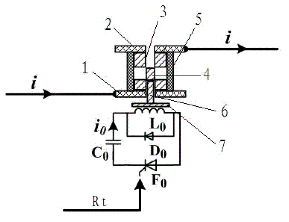
[0023] Such as figure 1 As shown, the present invention includes a repulsion drive circuit and a repulsion coil L connected in the repulsion drive circuit 0 . The repulsion drive circuit includes a capacitor C connected in series with a pre-charged voltage 0 , Thyristor F 0 and freewheeling diode D 0 , capacitor C 0 The positive and negative poles are respectively connected to the freewheeling diode D 0 Negative pole, thyristor F 0 Cathode connection, freewheeling diode D 0 Anode and thyristor F 0 anode connection, the repulsion coil is connected in series with the capacitor C 0 with thyristor F 0 between and with the freewheeling diode D 0 Parallel, Thyristor F 0 It turns on after receiving the trigger signal Rt from ...


PUM


Abstract

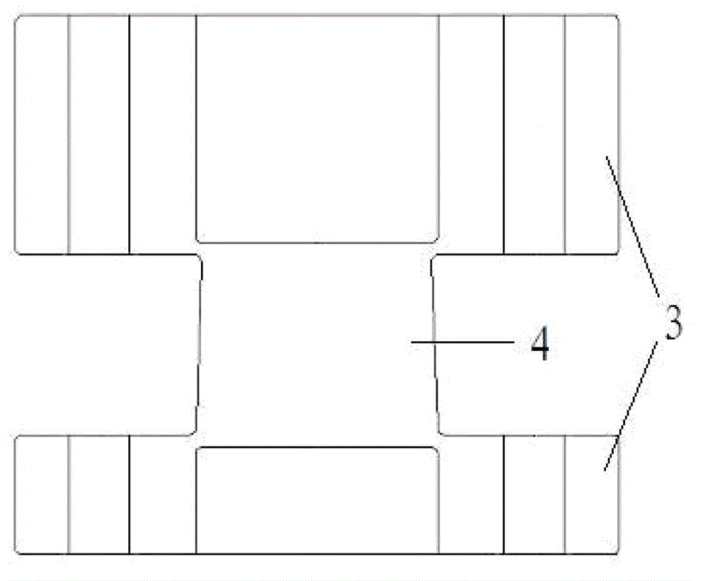
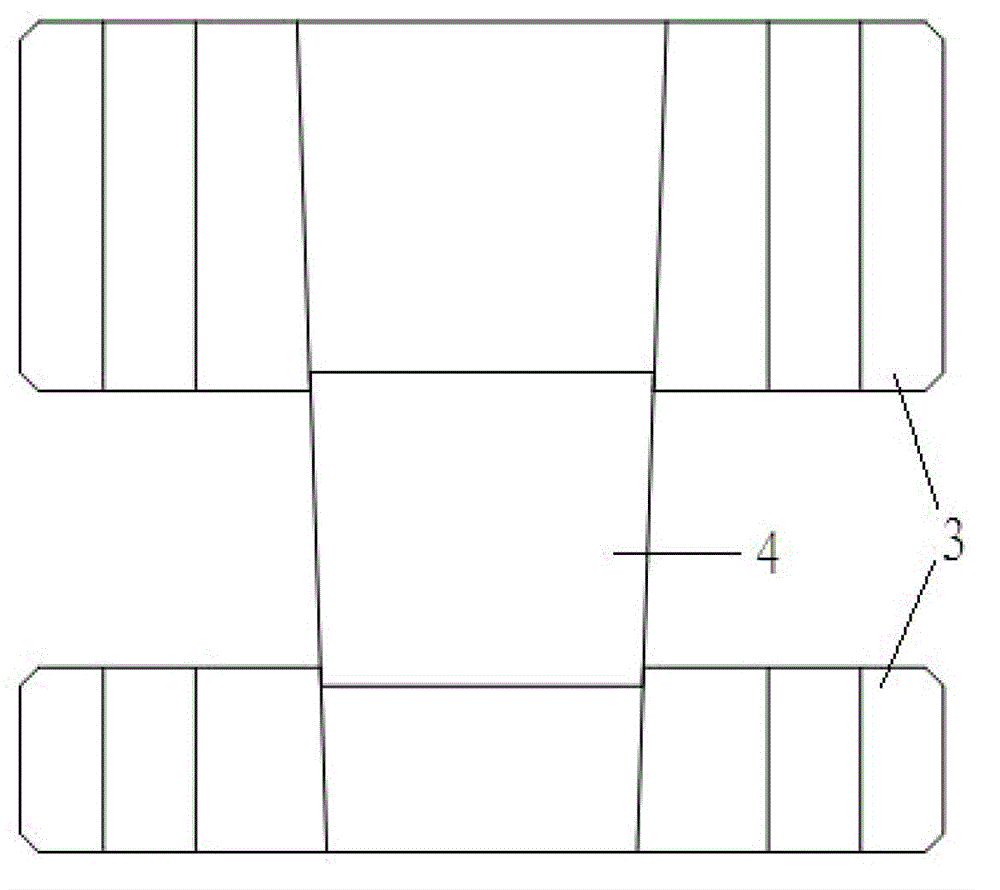
The invention relates to an interrupter for quick current-limiting interruption during a short trouble of a power grid, in particular to an electromagnetic-repulsion-driven high-speed piston type interrupter. The electromagnetic-repulsion-driven high-speed piston type interrupter comprises a repulsion driving circuit, a repulsion coil, an input connecting terminal and an output connecting terminal, wherein the repulsion coil is connected in the repulsion driving circuit, a bridge body is connected between the input connecting terminal and the output connecting terminal in a bridging mode, an insulating sleeve is sleeved outside the bridge body, a repulsion plate is arranged below the bridge body and located above the repulsion coil, and an insulting block capable of breaking the bridge body off is fixed on the repulsion plate. An electromagnetic repulsion driving technology replaces an explosive driving technology, and thus defects of the explosive driving technology are overcome. The structure that the bridge body is connected between the two connecting terminals serves as a through-current circuit, so not only are the temperature-rising requirements of circulation of a large current met, but also energy required by interruption of the interrupter is reduced. The cost is greatly reduced, the interrupting speed and the interrupting reliability are greatly promoted, and the electromagnetic-repulsion-driven high-speed piston type interrupter has wide prospects for engineering application and good economic benefits.

Description

technical field [0001] The invention relates to a breaker for fast current-limiting breaking when a short-circuit fault occurs in a power grid, in particular to a piston-type high-speed breaker driven by electromagnetic repulsion. Background technique [0002] With the increasing level of short-circuit current in the power grid, the peak value of short-circuit current can reach more than 100kA, and the rising rate of short-circuit current di / dt is extremely high. The limit breaking capacity of traditional circuit breakers is insufficient, and the operating time is long, so it is difficult to meet short-circuit faults. Requirements for fast current-limiting breaking. Installing a new fault current limiting device (FCL) in the power grid is an ideal solution to this kind of problem. Research on new current limiting devices with various principles has been carried out at home and abroad, such as superconducting current limiter, solid state current limiter, Liquid metal current...

Claims


Application Information

Patent Timeline
IPC IPC(8): H01H3/28
Inventor 庄劲武袁志方王晨张超徐国顺江壮贤
Owner NAVAL UNIV OF ENG PLA
Learn More