
a power cabinet

A technology for power cabinets and power components, applied in the field of power cabinets, can solve problems such as easy failure, fault expansion, arc short circuit, etc., and achieve the effects of improving detection accuracy, enhancing interchangeability, and reducing operating temperature

Active Publication Date: 2016-06-22
天津市科德电气成套有限公司
View PDF6 Cites 0 Cited by
  • Summary
  • Abstract
  • Description
  • Claims
  • Application Information

AI Technical Summary

Problems solved by technology

The existing power cabinets produced by other manufacturers mostly adopt integral air duct design, which is inconvenient to install and replace components, wastes a lot of circulating air, has poor heat dissipation effect, and cannot exert the maximum capacity of electrical components. For power supply equipment, only parallel schemes can be adopted, which has the disadvantages of high cost, complex system and prone to failure.
The size of the heat sink of the power component is not standard enough and the versatility is poor, and the overall weight of the profile is too light, and the heat dissipation area is small, which cannot meet the heat dissipation requirements of the thyristor
The fast fuse and the power component are set in the same air duct and there is no partition to separate them. When the fast fuse blows, it is very easy to cause arc short circuit, which is caused by fault expansion and unnecessary losses.

Method used


Image

  • a power cabinet
  • a power cabinet
  • a power cabinet

Examples


Embodiment Construction

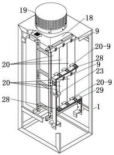
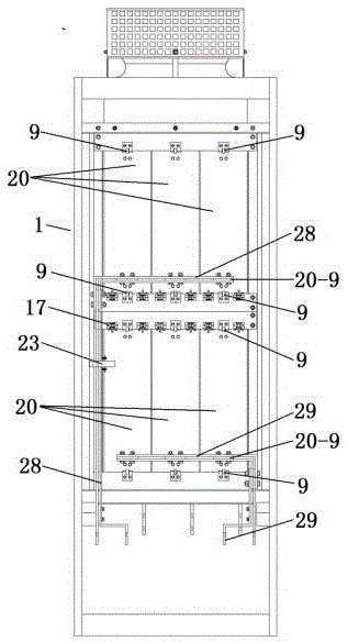
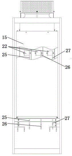
[0021] Such as Figure 1 to Figure 11 As shown, a power cabinet includes a cabinet 1 composed of a left side panel, a right side panel, a front door, a rear door, and an upper wind bucket 18 fixed on the frame, and also includes a power assembly 20, a fast fuse 22, and a current Hall sensor 23 , Current transformer 24, AC bus bar 1W125, AC bus bar 1V126, AC bus bar 1U127, DC bus bar 1C128, DC bus bar 1D129.

[0022] Power assembly 20, including radiator I20-1, radiator II20-2, radiator III20-3, front windshield 20-4, rear windshield 20-5, guide groove 20-6, connecting row 20-7 , AC side lead-out row 20-8, DC side lead-out row 20-9, thyristor 20-10, resistor 20-12, capacitor 20-13, also includes inner air duct plate 20-11, inner air duct plate 20-11 consists of Set as one vertical plate 20-11-1, upper horizontal plate 20-11-2 and lower horizontal plate 20-11-3 to form three.

[0023] Several ventilation holes 20-11-23 are symmetrically arranged on the upper horizontal plate 2...


PUM


Abstract

The invention relates to a power cabinet. Direct-current side lead-out bars of three sets of power components in a main air duct I, a main air duct II and a main air duct III on the upper portion inside a cabinet body are connected with a direct-current busbar 1C1 sleeved with a current Hall sensor; direct-current side lead-out bars of three sets of power components in a main air duct I, a main air duct II and a main air duct III on the lower portion inside the cabinet body are connected with a direct-current busbar 1D1; alternating-current side lead-out bars of two sets of power components in a main air duct I in a rear auxiliary air duct of the cabinet body are connected with an alternating-current busbar 1U1 sleeved with a current transformer through fast acting fuses respectively; alternating-current side lead-out bars of two sets of power components in the main air ducts II are connected with an alternating-current busbar 1V1 through fast acting fuses respectively; alternating-current side lead-out bars of two sets of power components in the main air ducts III are connected with an alternating-current busbar 1W1 sleeved with a current transformer through fast acting fuses respectively; because of main air duct structures, interchangeability of products is enhanced; by means of the auxiliary air duct structure, fast heat dissipation can be achieved, and input buses can be protected. Instantaneous overload of equipment capacity can reach 4500 A because of structural design of the power components.

Description

technical field [0001] The invention relates to a power cabinet, which is widely used in metallurgical industry, hoisting industry, electric locomotive and other fields, and is mainly used for the transformation and expansion of the original DC speed regulation system. Background technique [0002] At present, in the international and domestic transmission industries, most of the DC transmission drive systems adopt the scheme of restructuring and expansion. A key link of the restructuring and expansion scheme is the expansion of the armature circuit. The existing power cabinets produced by other manufacturers mostly adopt integral air duct design, which is inconvenient to install and replace components, wastes a lot of circulating air, has poor heat dissipation effect, and cannot exert the maximum capacity of electrical components. For power supply equipment, only parallel schemes can be adopted, which has disadvantages such as high cost and complex system prone to failure. ...

Claims


Application Information

Patent Timeline
Patent Type & Authority Patents(China)
IPC IPC(8): H02M1/00H05K7/20H05K5/02H05K7/02
Inventor 葛文彬
Owner 天津市科德电气成套有限公司
Learn More