Mobile terminal and power control method thereof

A mobile terminal, power technology, applied in the direction of electrical components, circuit devices, electromagnetic wave systems, etc., can solve problems such as the deterioration of receiving sensitivity, and achieve the effect of preventing deterioration

Inactive Publication Date: 2013-10-23
LG INNOTEK CO LTD
View PDF3 Cites 0 Cited by
  • Summary
  • Abstract
  • Description
  • Claims
  • Application Information

AI Technical Summary

Problems solved by technology

[0007] However, when a call signal is received in a related art mobile terminal during a wireless power transmission process, communication jamming is caused by a magnetic field generated during power transmission, so that reception sensitivity is degraded.

Method used


Image

  • Mobile terminal and power control method thereof
  • Mobile terminal and power control method thereof
  • Mobile terminal and power control method thereof

Examples


Embodiment Construction

[0027] Hereinafter, exemplary embodiments will be described in detail with reference to the accompanying drawings so that those skilled in the art can easily implement the embodiments.

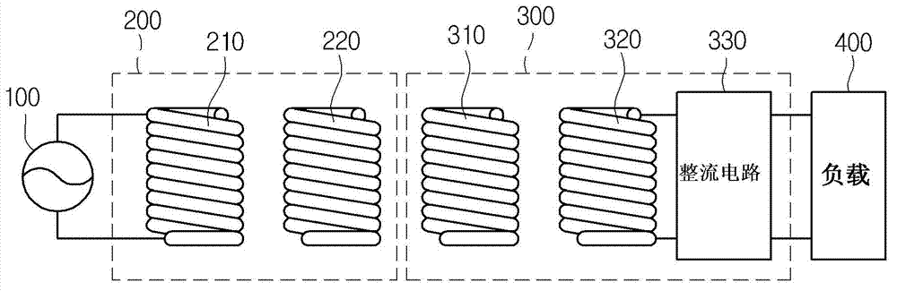
[0028] figure 1 is a circuit diagram showing the resonance type wireless power transmission system 1000 according to the embodiment.

[0029] refer to figure 1 , the wireless power transmission system 1000 may include a power supply device 100 , a wireless power transmitter 200 , a wireless power receiver 300 , and a load 400 .

[0030] According to one embodiment, the power supply device 100 may be included in the wireless power transmitter 200 .

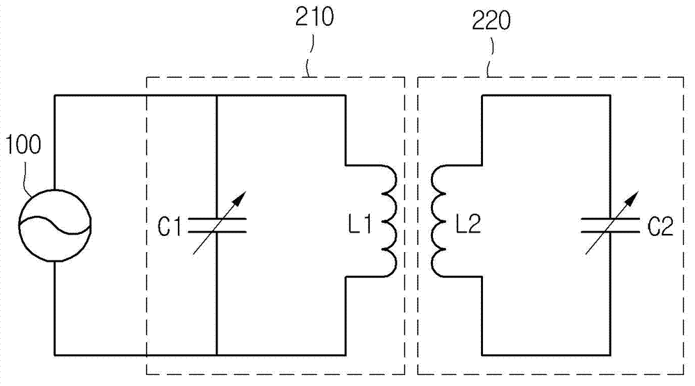
[0031] The wireless power transmitter 200 may include a transmission induction coil 210 and a transmission resonance coil 220 .

[0032] The wireless power receiver 300 may include a reception resonance coil 310 , a reception induction coil 320 , a rectification circuit 330 and a load 400 .

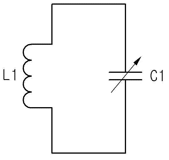
[0033] Two terminals of the power supply device 100 ...


PUM


Abstract

Disclosed is a mobile terminal. The mobile terminal includes a receiving unit to wirelessly receive power from a wireless power transmitter; and a sensing unit to sense a call signal, wherein, when the call signal is sensed, the mobile terminal transmits a transmission power control signal for controlling transmission power of the wireless power transmitter to the wireless power transmitter.

Description

technical field [0001] The present disclosure relates to a wireless power transmission technology. More particularly, the present disclosure relates to a mobile terminal capable of wirelessly receiving power using a wireless power transmission technology and a power control method thereof. Background technique [0002] Wireless power transmission or wireless energy transfer refers to a technique of wirelessly transferring power to a desired device. In the 19th century, a motor or a transformer employing the principle of electromagnetic induction has been widely used, and then a method for transmitting electric energy by radiating electromagnetic waves such as radio waves or laser has been proposed. Actually, an electric toothbrush or an electric razor frequently used in daily life is charged based on the principle of electromagnetic induction. Electromagnetic induction refers to a phenomenon in which voltage is induced so that current flows when a magnetic field around a c...

Claims


Application Information

Patent Timeline
Patent Type & Authority Applications(China)
IPC IPC(8): H02J17/00
CPCH04B5/0037H04W52/50H02J50/12H02J50/80H02J7/00034H04B5/24H04B5/79
Inventor 李钲五李奇珉
Owner LG INNOTEK CO LTD
Why Eureka
Try Eureka