Eureka AIR delivers breakthrough ideas for toughest innovation challenges, trusted by R&D personnel around the world.

Device for recycling waste heat generated in procedure of acid making and conversion of sulphide ore

A technology of waste heat recovery and sulfide ore, applied in the direction of steam generation using heat carrier, etc., can solve the problems of long pipes, smoke from chimneys, high cost, etc., and achieve compact equipment, easy maintenance and high heat transfer efficiency Effect

Inactive Publication Date: 2012-10-31
SHANDONG BOFENG LIZHONG CHEM
View PDF3 Cites 2 Cited by
  • Summary
  • Abstract
  • Description
  • Claims
  • Application Information

AI Technical Summary

Problems solved by technology

[0002] The conversion process is mainly to convert SO from purified and dried 2 The gas reacts with oxygen through the vanadium catalyzer to convert it into SO 3 , and then supplied to the dry suction post to make sulfuric acid. The traditional view is that the conversion process of pyrite acid production only needs to maintain the heat balance of the converter itself. Therefore, many pyrite acid production enterprises have not recycled the surplus heat of the conversion process for many years. , but SO 3 The dew point of the flue gas is relatively low, and the traditional waste heat boiler is prone to dew point corrosion, causing water vapor to enter the converter and absorption tower, resulting in catalyst pulverization and a large amount of smoke from the chimney
Although our company starts to recover and utilize the excess heat in the conversion process of pyrite acid production, the conversion process is far away from the boiler and feed water pump. If an economizer is added to heat the boiler feed water, the pipeline is long and expensive.

Method used


Image

  • Device for recycling waste heat generated in procedure of acid making and conversion of sulphide ore
  • Device for recycling waste heat generated in procedure of acid making and conversion of sulphide ore

Examples


Embodiment Construction

[0010] Embodiments of the present invention are further described below in conjunction with accompanying drawings:

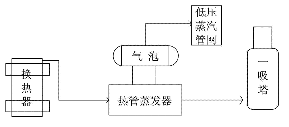
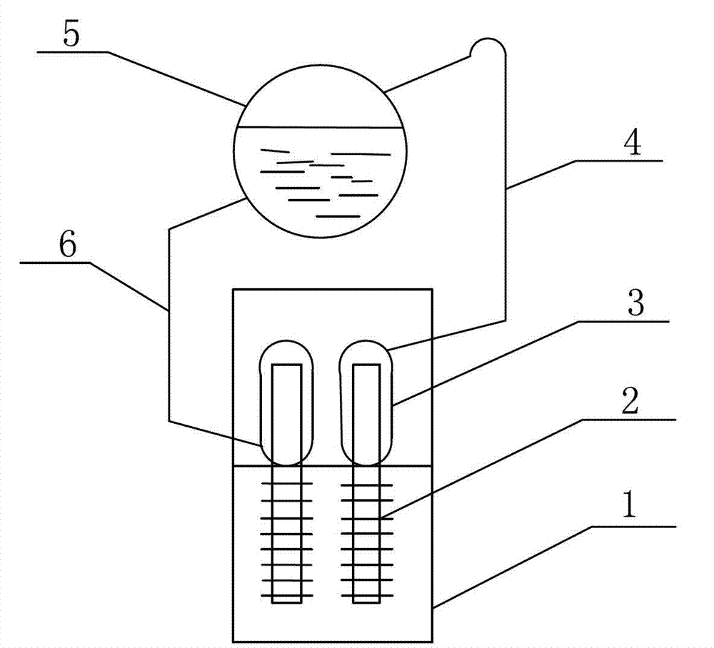
[0011] Such as Figure 1-2 As shown, a waste heat recovery and utilization device in the acid conversion process of sulfide ore, including a heat exchanger and a suction tower, a heat pipe evaporator is installed between the heat exchanger and a suction tower, and the heat pipe evaporator is incorporated into the low-pressure steam through the steam drum Pipe Network. The heat pipe evaporator includes a flue gas channel 1, a heat pipe 2, a water jacket 3, an ascending pipe 4, a steam drum 5 and a downcomer 6. The heat pipe 2 is arranged inside the flue gas passage 1, and the upper end of the heat pipe 2 is respectively provided with a water jacket 3 and a water jacket. 3 is connected to the steam drum 5 through the ascending pipe 4, and the steam drum 5 is connected to another water jacket 3 through the descending pipe 6.

[0012] Working principle and usage p...


PUM


Abstract

The invention provides a device for recycling waste heat generated in a procedure of acid making and conversion of sulphide ore, belonging to the field of recycling residual heat resources. The device for recycling the waste heat generated in the procedure of acid making and conversion of sulphide ore comprises a heat exchanger and an absorption tower, and is characterized in that a connecting heat pipe evaporator is arranged between the heat exchanger and the absorption tower, and the heat pipe evaporator is merged into a low-pressure steam through a steam manifold. The heat pipe evaporator comprises a flue gas channel (1), a heat pipe (2), water sleeves (3), an ascending pipe (4), a steam manifold (5) and a descending pipe (6), wherein the heat pipe (2) is arranged in the flue gas channel (1), the water sleeves (3) are respectively arranged on the upper end of the heat pipe (2), the water sleeve (3) is connected with the steam manifold (5) through the ascending pipe (4), the steam manifold (5) is connected with another water sleeve (3) through the descending pipe (6). The device has the advantages of small flow resistance, high heat transfer efficiency, compact device structure, light weight, and convenience for maintenance, and effectively prevents the boiler feed water from leaking in the fuel gas channel.

Description

technical field [0001] The invention relates to a waste heat recovery and utilization device in the conversion process of sulfide ore acid production, which belongs to the field of waste heat resource reuse. Background technique [0002] The conversion process is mainly to use the purified and dried SO 2 The gas reacts with oxygen through the vanadium catalyzer to convert it into SO 3 , and then supplied to the dry suction post to make sulfuric acid. The traditional view is that the conversion process of pyrite acid production only needs to maintain the heat balance of the converter itself. Therefore, many pyrite acid production enterprises have not recycled the surplus heat of the conversion process for many years. , but SO 3 The dew point of flue gas is relatively low, and traditional waste heat boilers are prone to dew point corrosion, causing water vapor to enter the converter and absorption tower, resulting in catalyst pulverization and a large amount of smoke from th...

Claims


Application Information

Patent Timeline
IPC IPC(8): F22B1/18
Inventor 宾光年刘涛袁勇董贵平李胜良
Owner SHANDONG BOFENG LIZHONG CHEM
Why Eureka
Eureka Blog
Learn More