Unlock instant, AI-driven research and patent intelligence for your innovation.

Synchronous rectification driving circuit

A synchronous rectification and drive circuit technology, applied in electrical components, conversion devices for converting AC power input to DC power output, and output power, etc., can solve the problems of narrow input voltage range, complex circuit structure, poor reliability, etc. The effect of rectifier Q2 gate-source breakdown, high reliability and low cost

Active Publication Date: 2013-10-23
BEIJING SUPLET +1
View PDF5 Cites 5 Cited by
  • Summary
  • Abstract
  • Description
  • Claims
  • Application Information

AI Technical Summary

Problems solved by technology

[0004] In view of this, the purpose of this application is to provide a synchronous rectification driving circuit to solve the problems of narrow input voltage range of existing self-driving and winding direct driving methods and complex circuit structure, high cost and poor reliability of other driving methods

Method used


Image

  • Synchronous rectification driving circuit
  • Synchronous rectification driving circuit
  • Synchronous rectification driving circuit

Examples


Embodiment Construction

[0037] The following will clearly and completely describe the technical solutions in the embodiments of the application with reference to the drawings in the embodiments of the application. Apparently, the described embodiments are only some of the embodiments of the application, not all of them. Based on the embodiments in this application, all other embodiments obtained by persons of ordinary skill in the art without creative efforts fall within the protection scope of this application.

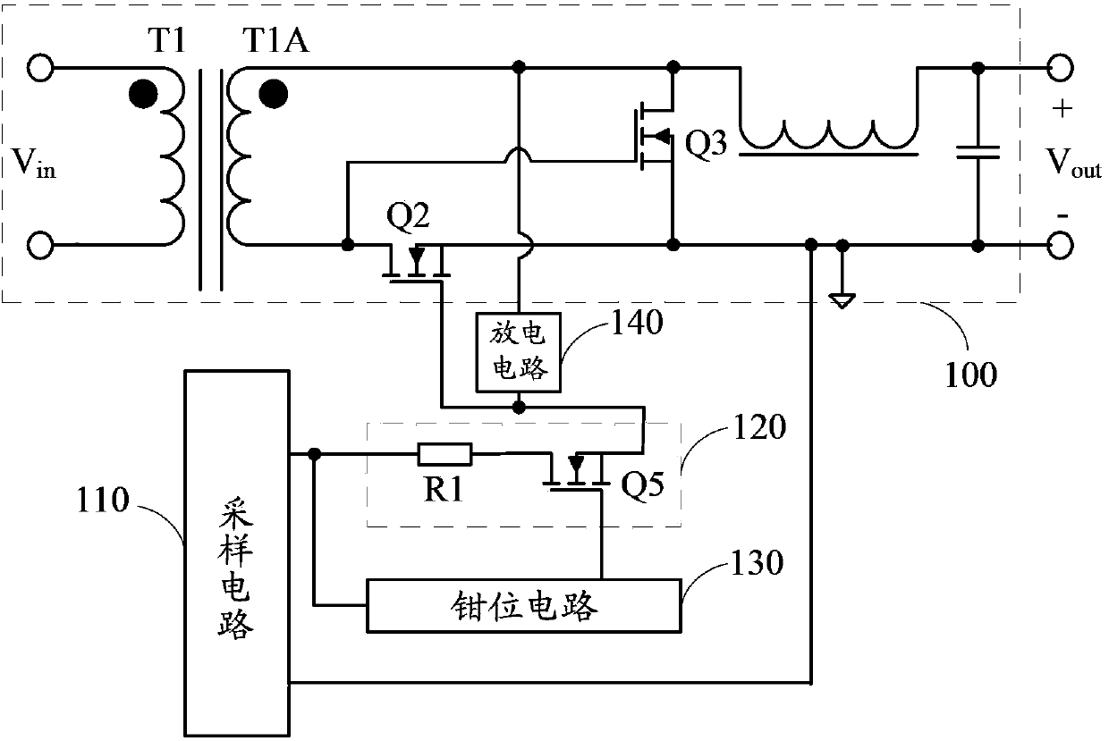
[0038] The embodiment of the present application discloses a synchronous rectification drive circuit to solve the problems of narrow input voltage range of existing self-drive and winding direct drive methods and complex circuit structure, high cost and poor reliability of other drive methods.

[0039] Embodiment 1 of the present application provides a synchronous rectification driving circuit, which is applied to a synchronous rectification circuit. Generally, the synchronous rectification...


PUM


Abstract

The invention discloses a synchronous rectification driving circuit, comprising a sampling circuit, a main driving circuit, a clamping circuit and a discharging circuit, wherein the sampling circuit is used for acquiring and outputting a sampling voltage for representing the size of an input voltage of the synchronous rectification circuit; the main driving circuit is used for controlling the alternated connection of a rectifying tube and a follow current tube; when the rectifying tube is connected, the clamping circuit is used for performing clamping on a grid voltage of a switching tube; when the follow current tube is connected, the discharging circuit enables a grid electrode of the rectifying tube to discharge so as to enable the rectifying tube to be rapidly turned off; the main driving circuit comprises a first resistor and the switching tube. The driving voltage of the rectifying circuit is controlled by virtue of voltage splitting of the switching tube, clamping of the clamping circuit and discharging of the discharging circuit, a positive high voltage and a negative high voltage are prevented from forming at the grid electrode and a source electrode of the rectifying tube under the condition of input within a wide voltage range, and the hidden danger of puncturing the grid and source electrodes of the rectifying tube by an extremely high input voltage is avoided. The synchronous rectification driving circuit is simple in structure, low in cost and high in reliability and solves the problems in the prior art.

Description

technical field [0001] The present application relates to the technical field of power electronics, in particular to a synchronous rectification drive circuit. Background technique [0002] In the field of electronic technology, the application of synchronous rectification technology is more and more extensive. The key to synchronous rectification technology is the drive technology. Common drive methods include self-drive, winding direct drive and other drive. Among them, the self-drive and winding direct drive methods are difficult to balance the positive and negative driving voltages under the input conditions of a wide voltage range, and both may have the problem of excessively high positive and negative driving voltages, resulting in breakdown of the rectifier tube, so they can only be applied to Under the condition that the input voltage range is narrow; the circuit structure of the driving mode is complicated, the cost is high, and the reliability is poor. [0003] T...

Claims


Application Information

Patent Timeline
Patent Type & Authority Applications(China)
IPC IPC(8): H02M7/217
Inventor 尹安全金祖敏
Owner BEIJING SUPLET