
Switchover method and device for main equipment and standby equipment

A technology of active equipment and standby equipment, which is applied in the field of communication, and can solve problems such as the inability to switch between active and standby equipment, the inability of the VRRP redundancy group 110 to perceive, and the inability to perceive link failures of transmission equipment, etc.

Inactive Publication Date: 2013-10-23
HUAWEI TECH CO LTD
View PDF4 Cites 22 Cited by
  • Summary
  • Abstract
  • Description
  • Claims
  • Application Information

AI Technical Summary

Problems solved by technology

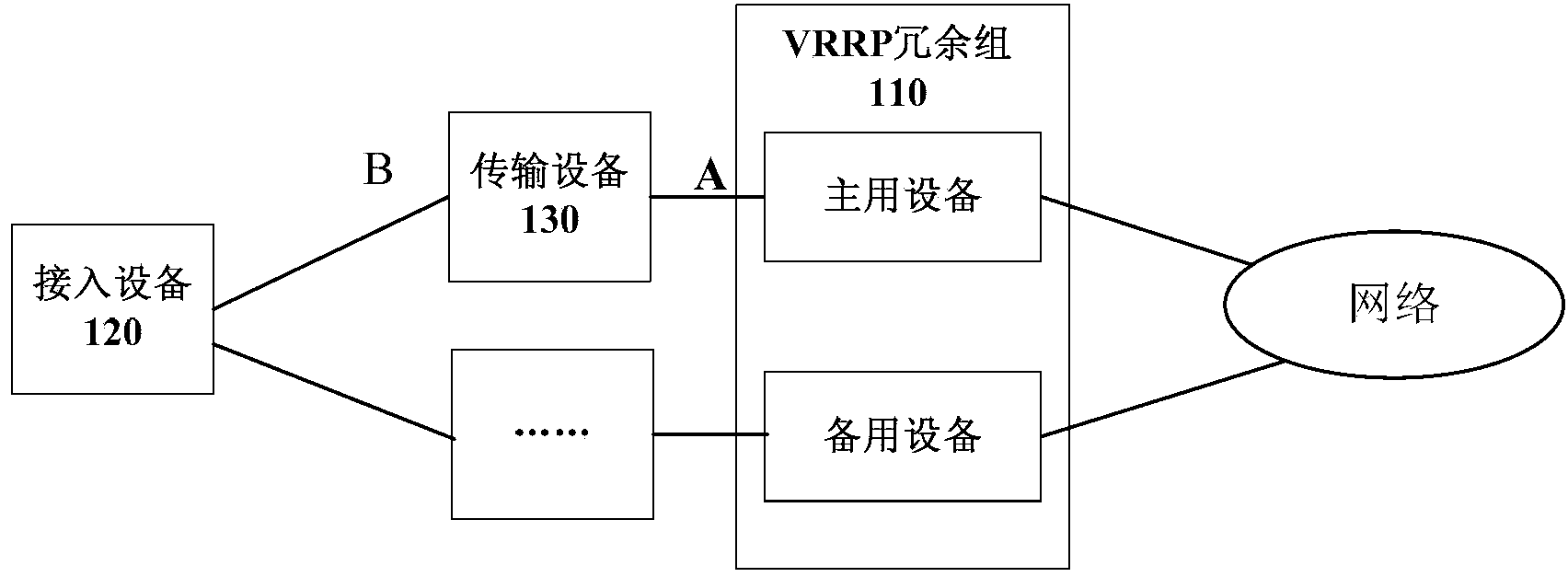
When other segment links (such as figure 1 When the B-segment link in the VRRP group fails, the VRRP redundancy group 110 cannot detect it, that is, it cannot switch between the active and standby devices
[0004] In the existing technology, Ethernet-Operation Administration and Maintenance (ETH-OAM) can be deployed on all devices to solve the problem that the VRRP redundancy group cannot perceive the link failure between two transmission devices. question
ETH-OAM configuration is relatively complicated. If there are many access devices connected to the VRRP redundancy group 110 through the transmission device 130, the configuration amount will be large, and more OAM signaling will occupy the normal bandwidth of the device.
In addition, this method requires that all devices must support ETH-OAM, and the devices must be seamlessly interconnected. If a certain device on the link does not support ETH-OAM, the VRRP redundancy group cannot perceive the connection The link failure between the ingress device 120 and the transmission device 130 or between two transmission devices makes it impossible to switch between the active and standby devices

Method used


Image

  • Switchover method and device for main equipment and standby equipment
  • Switchover method and device for main equipment and standby equipment
  • Switchover method and device for main equipment and standby equipment

Examples


Embodiment Construction

[0030] In order to make the object, technical solution and advantages of the present invention clearer, the present invention will be further described in detail below in conjunction with the accompanying drawings. Obviously, the described embodiments are only some embodiments of the present invention, rather than all embodiments . Based on the embodiments of the present invention, all other embodiments obtained by persons of ordinary skill in the art without making creative efforts belong to the protection scope of the present invention.

[0031] Firstly, an application scenario of a method for switching a master device and a backup device provided by the present invention is introduced. Such as figure 2As shown, in this scenario, the redundancy group 210 with the routing function includes: the active device 211 and the backup device 212, and the access device 220 is connected to the active device 211 and the backup device 212 respectively. Between the access device 220 an...


PUM


Abstract

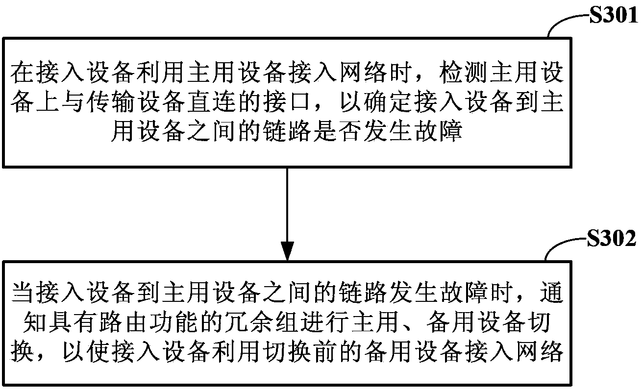
The invention relates to a switchover method and device for main equipment and standby equipment. The switchover method for the main equipment and the standby equipment comprises the following steps that when access equipment accesses the network through the main equipment, the interface directly connected with the access equipment or transmission equipment on the main equipment is detected to determine whether the link from the access equipment to the main equipment breaks down, and when the link from the access equipment to the main equipment breaks down, a redundancy set with a routing function is informed to carry out switchover between the main equipment and the standby equipment so that the access equipment can access the network through the standby equipment before switchover.

Description

technical field [0001] The invention relates to the technical field of communications, in particular to a method and device for switching between master and backup equipment. Background technique [0002] At present, the development of the network is changing with each passing day. With the rapid popularization of the network and the deepening of the application, various value-added services have been widely deployed on the network, and the network bandwidth has also increased exponentially. A short-term interruption of the network may affect a large number of services, causing huge loss. As the basic network that carries the business, its reliability has become the focus of increasing attention. Virtual Router Redundancy Protocol (VRRP) is such a reliability technology, which can implement redundant backup of network devices and improve network reliability. [0003] When using VRRP technology in a real network, such as figure 1 As shown, usually there may be one or more ...

Claims


Application Information

Patent Timeline
Patent Type & Authority Applications(China)
IPC IPC(8): H04L1/22H04L12/703H04L12/24H04L45/24H04L45/28
CPCH04L1/22H04L45/22H04L45/28H04L69/40H04L41/0654
Inventor 苗成林张强文双全孟凡路陈卫
Owner HUAWEI TECH CO LTD
Learn More