LED drive circuit

A technology of LED drive and circuit, applied in the direction of lamp circuit layout, electric light source, lighting device, etc., can solve the problems of high cost and complicated drive circuit, and achieve the effect of simple and reliable circuit, scattered heat loss and reasonable setting

Inactive Publication Date: 2013-10-23
ANHUI SHILIN LIGHTING
View PDF4 Cites 3 Cited by
  • Summary
  • Abstract
  • Description
  • Claims
  • Application Information

AI Technical Summary

Problems solved by technology

[0002] With the continuous improvement of light efficiency, LED has been greatly developed as a lighting source in recent years. Compared with incandescent l

Method used


Image

  • LED drive circuit

Examples


Example Embodiment

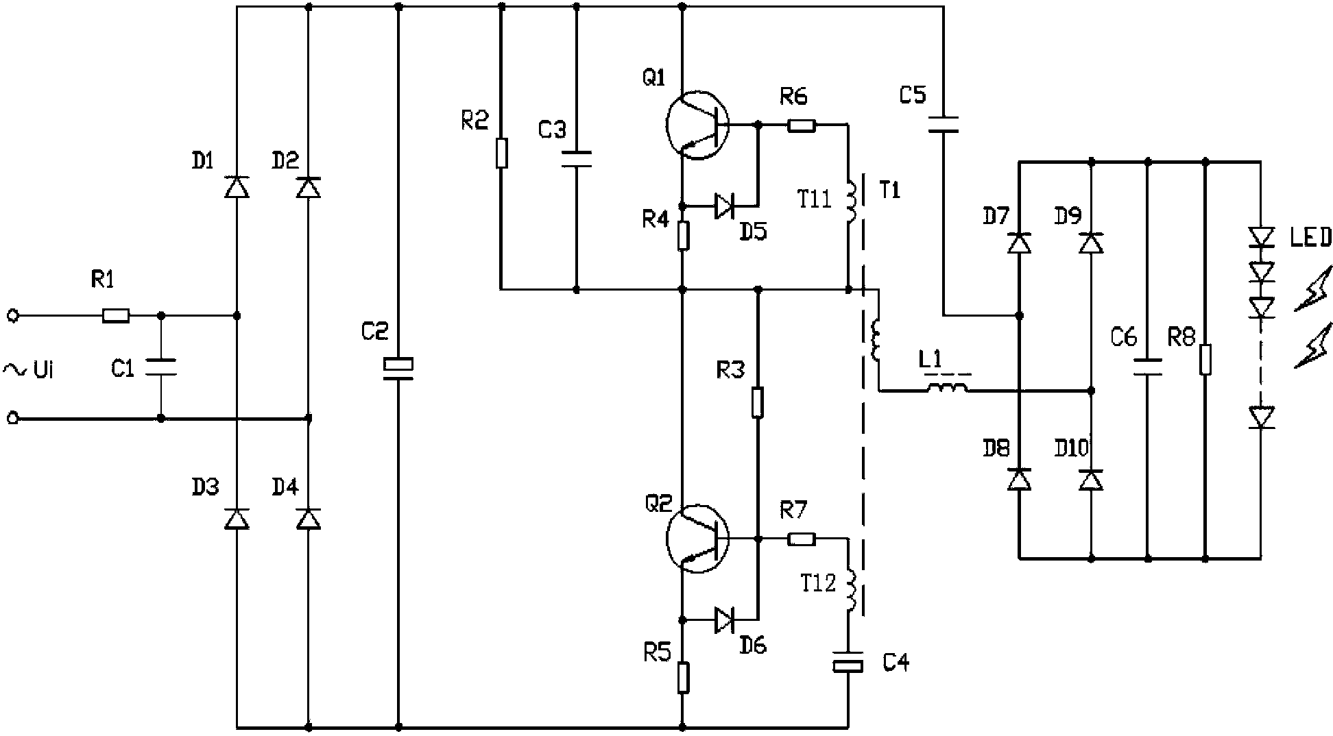
[0009] Such as figure 1 As shown, an LED drive circuit, the power Ui is connected to the two AC input ports of the rectification filter circuit composed of diodes D1, D2, D3 and D4 through the fuse resistor R1 and the X capacitor C1, and the rectification output positive and the output of the rectification filter circuit The capacitor C2 is connected between the negative poles, the collector of the transistor Q1 is connected to the output positive pole of the rectifier filter circuit, the emitter of the transistor Q1 is connected to the collector of the transistor Q2 through the bias resistor R4, and the emitter of the transistor Q2 is connected to the rectifier through the bias resistor R5 The output cathode of the filter circuit, diode D5 and diode D6 are respectively connected between the base and emitter of transistor Q1 and transistor Q2, resistor R2 and resistor R3 are connected in series, resistor R2 is connected with the output anode of the rectifier filter circuit, resi...


PUM


Abstract

The invention discloses an LED drive circuit. A power source Ui is connected with two alternating current input ports of a rectification and filter circuit through a safety resistor R1 and an X capacitor C1, wherein the rectification and filter circuit is formed by a diode D1, a diode D2, a diode D3 and a diode D4. A capacitor C2 is connected between a rectification output positive pole and a rectification output negative pole of the rectification and filter circuit. A collector of an audion Q1 is connected with an output positive pole of the rectification and filter circuit, an emitter of the audion Q1 is connected with a collector of an audion Q2 through a biasing resistor R4, an emitter of the audion Q2 is connected with an output negative pole of the rectification and filter circuit through a biasing resistor R5, a diode D5 and a diode D6 are connected between a base of the audion Q1 and a base of the audion Q2, and between the collector of the audion Q1 and the collector of the audion Q2 respectively, a resistor R2 and a resistor R3 are connected in series, the resistor R2 is connected with the output positive pole of the rectification and filter circuit, and the resistor R3 is connected with the base of the audion Q2. According to the LED drive circuit, control over drive current can be achieved while an expensive IC is not needed; the circuit is simple and reliable and low in cost; discrete components are adopted, therefore, thermal loss is dispersed, and the circuit will be more stable; component diameters are arranged reasonably, and therefore power consumption is lower than that of the IC.

Description

technical field [0001] The invention relates to the technical field of LEDs, in particular to an LED driving circuit. Background technique [0002] With the continuous improvement of light efficiency, LED has been greatly developed as a lighting source in recent years. Compared with incandescent lamps, the driving circuit of LED is much more complicated, and IC circuits are mostly used to complete complex functions, and its cost is also high. No more. Contents of the invention [0003] The object of the present invention is to provide an LED driving circuit in order to remedy the defects of the prior art. [0004] The present invention is achieved through the following technical solutions: [0005] An LED drive circuit, the power supply Ui is connected to the two AC input ports of the rectification filter circuit composed of diodes D1, D2, D3 and D4 through the insurance resistor R1 and the X capacitor C1, between the rectification output positive pole and the output...

Claims


Application Information

Patent Timeline
IPC IPC(8): H05B37/02
Inventor 李运鹤桑永树刘军
Owner ANHUI SHILIN LIGHTING
Why Eureka
Try Eureka